Axial locking mechanism of machine tool spindle

An axial locking, machine tool spindle technology, applied in metal processing equipment and other directions, can solve the problems of rapid precision loss, large motor power, and large heat generation, and achieve the effect of increasing static rigidity, dynamic rigidity, and rigidity.

Inactive Publication Date: 2012-10-17
湖南金能达机电科技有限公司 +1
View PDF5 Cites 4 Cited by
  • Summary
  • Abstract
  • Description
  • Claims
  • Application Information

AI Technical Summary

Problems solved by technology

The tangential clamping mechanism is suitable for the case where the shaft diameter is small, such as the clamping of the top shaft of the tailstock; the radial hydraulic clamping mechanism uses hydraulic pressure to slightly deform the thin-walled parts in the hydraulic device, hold the main shaft tightly, and tighten the thin-walled parts. The process requirements of the wall parts are high, and it is easy to cause the phenomenon that it cannot be released after clamping, and it is difficult to realize the semi-clutch working state and stop self-locking; for the high-torque spindle, the double driven wheel gear anti-backlash mechanism cannot meet the requirements, and only double Drive wheel anti-backlash mechanism is expensive; worm wheel and worm anti-backlash mechanism uses double worm mechanism, which is relatively expensive and difficult to adjust. There is also a double-lead worm anti-backlash mechanism, but it wears quickly The life is short, and the corresponding loss of precision is also fast; when the motor direct drive is realized, the required motor power is large, the heat generation is large, and the cost is relatively high

Method used


Image

  • Axial locking mechanism of machine tool spindle
  • Axial locking mechanism of machine tool spindle
  • Axial locking mechanism of machine tool spindle

Examples


Embodiment Construction

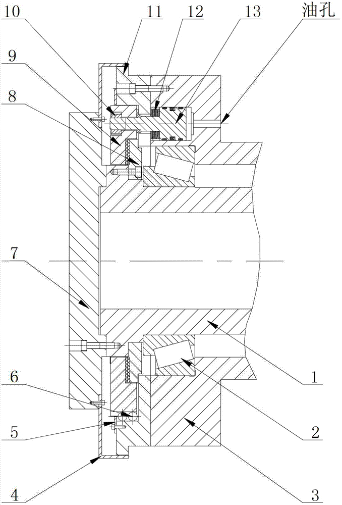
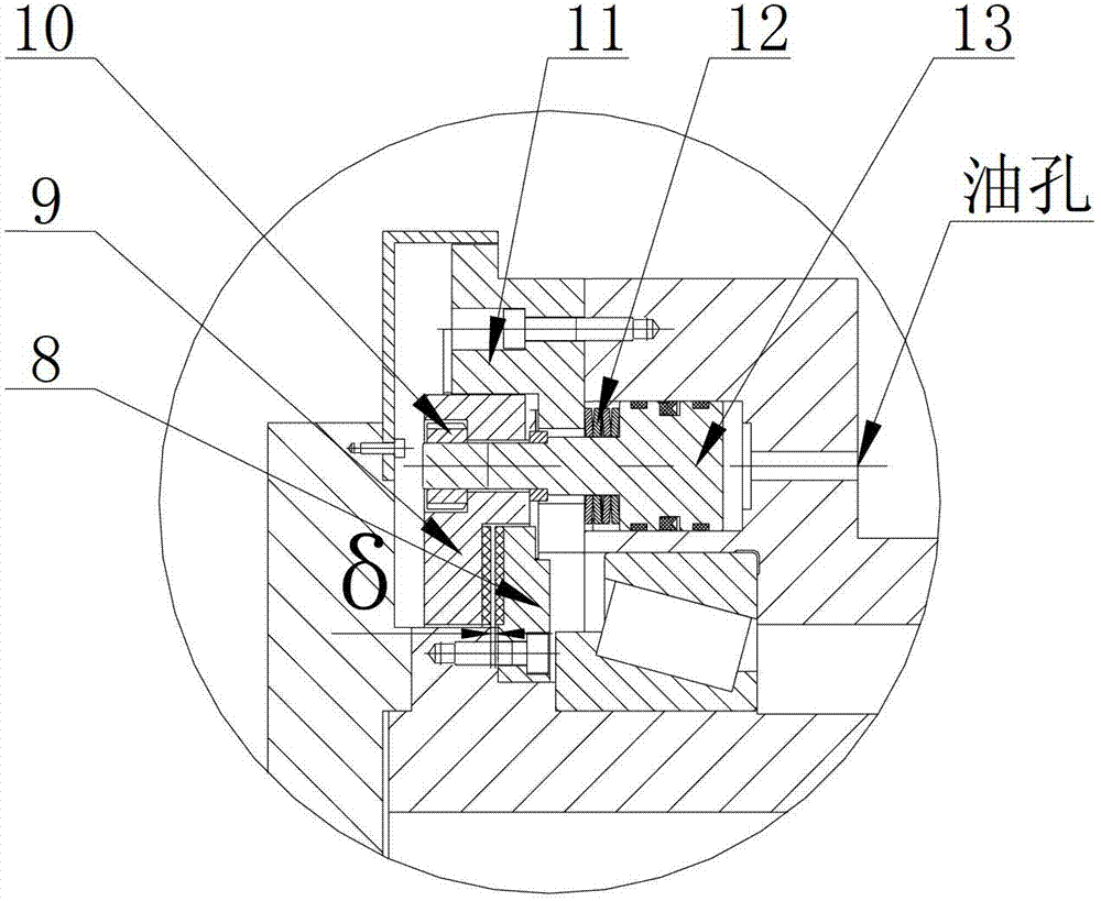
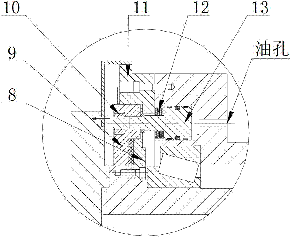
[0019] Below in conjunction with accompanying drawing and specific embodiment the present invention is described in further detail:

[0020] See attached figure 1 , 2 , 3. A machine tool spindle axial locking mechanism of the present invention, comprising a spindle (1), a spindle housing (3), a fixed friction ring (8), a dynamic friction ring (9), a spring (12), and an oil cylinder (13) , the fixed friction ring (8) and the dynamic friction ring (9) are both annular structures, and one side of the ring is provided with a friction plate with a matching position and shape, and the fixed friction ring (8) is fixed At one end of the main shaft (1), the outer circumference of the dynamic friction ring (9) is embedded in the guide ring (11) and sleeved on the main shaft case (3), and is located in the fixed friction ring (8) one side, and the friction plates provided on one side of the fixed friction ring (8) and the dynamic friction ring (9) correspond to each other; an oil cylin...


PUM


Abstract

The invention discloses an axial locking mechanism of a machine tool spindle, comprising a spindle, a spindle box body, a fixed friction ring, a movable friction ring, a spring and an oil cylinder, wherein friction sheets which have position and shape corresponding to the fixed friction ring and the movable friction ring are respectively arranged on the side surfaces of the fixed friction ring and the movable friction ring, the fixed friction ring is fixedly installed at one end of the spindle, the movable friction ring is sleeved on the spindle box body through a guide ring and is arranged at one side of the fixed friction ring, the spindle box body is provided with the oil cylinder, a piston is arranged in the oil cylinder, one end of the piston is fixedly connected with the movable friction ring, the spring which is arranged between the piston and one end surface of the oil cylinder is also sleeved on the piston, and the other end of the oil cylinder is communicated with a pressure oil device. The axial locking mechanism of the machine tool spindle has a simple and reasonable structure and is suitable for realizing industrial production as an axial locking device of the machine tool spindle; and with the adoption of the axial locking mechanism of the machine tool spindle, three working states including high speed running, self-clutching low speed rotation and complete locking of the machine tool spindle can be supplied, and the rigidity of the spindle under various working states is effectively improved.

Description

technical field [0001] The invention relates to an axial locking mechanism of a machine tool spindle, which belongs to the technical field of machine tool transmission structures. Background technique [0002] Technicians in the machine tool industry know that in actual production applications, we often use such a situation, when the spindle is rotated to a certain position, the spindle is positioned so that it does not rotate anymore, or the rotation is small for a long period of time Angle, and these spindles are used in high-precision machine tools, in addition to the accuracy needs to be guaranteed, good rigidity is also required. At present, the following types are commonly used at home and abroad: ① Tangential clamping mechanism; ② Radial hydraulic clamping mechanism; ③ Gear anti-backlash mechanism; ④ Worm gear and worm anti-backlash mechanism; ⑤ Motor direct drive, etc. The tangential clamping mechanism is suitable for the case where the shaft diameter is small, such...

Claims


Application Information

Patent Timeline
Patent Type & Authority Applications(China)
IPC IPC(8): B23B19/02
Inventor 陈敢汪中厚王锦华龙建国周鹤群
Owner 湖南金能达机电科技有限公司
Why Eureka
Try Eureka