Pneumatic slag removing device

A pneumatic and air inlet technology, which is applied in filing/filing device, filing/filing device, metal processing equipment, etc. The effect of reducing labor intensity, improving adaptability, and improving the efficiency of slag removal operations

Inactive Publication Date: 2012-10-17
WUXI CITY UNITE PETRO CHEM EQUIP
View PDF7 Cites 4 Cited by
  • Summary
  • Abstract
  • Description
  • Claims
  • Application Information

AI Technical Summary

Problems solved by technology

[0003] If the length of the cut is relatively long and the shape of the cut is complicated, using a chisel to remove the iron slag will lead to a significant decrease in work efficiency and a significant increase in labor intensity; The removal of iron slag by the grinder is not easy to remove the

Method used


Image

  • Pneumatic slag removing device
  • Pneumatic slag removing device

Examples


Embodiment Construction

[0016] The present invention will be described in detail below in conjunction with the implementations shown in the drawings, but it should be noted that these implementations are not limitations of the present invention, and those of ordinary skill in the art based on the functions, methods, or structural changes made by these implementations Equivalent transformations or substitutions all fall within the protection scope of the present invention.

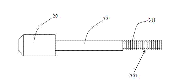
[0017] Please refer to figure 1 as shown, figure 1 It is a structural schematic diagram of a specific embodiment of a pneumatic slag removal device of the present invention. In this embodiment, a pneumatic slag removal device 100 includes: a cylinder body 10, a piston 20, a piston rod 30, the piston rod 30 is fixedly connected to the piston 20 and protrudes out of the cylinder body 10, and a rear end cover 40 And spring 50.

[0018] In this embodiment, the cylinder body 10 is fixedly connected to the rear end cap 40 , more spec...


PUM


Abstract

The invention provides a pneumatic slag removing device, which comprises a cylinder, a piston and a piston rod, wherein the piston rod is fixedly connected with the piston and extends out of the cylinder, a rear end cover and a spring; the cylinder is fixedly connected with the rear end cover; the side wall of the cylinder is provided with an exhaust hole; an air inlet is formed in the center of the rear end cover; the spring is arranged around the piston rod and positioned in the cylinder; two ends of the spring are respectively clamped by the piston and the cylinder; and a file head is arranged at one end of the piston rod, which is far away from the piston. According to the pneumatic slag removing device, the piston rod is driven to longitudinally reciprocate through longitudinal reciprocating motion of the piston in the cylinder, and iron slag at slits is removed through the cylindrical file head at the end of the piston rod, so that the slag removing efficiency is remarkably improved, the labor intensity of workers is reduced, and adaptability of the pneumatic slag removing device is also improved.

Description

technical field [0001] The invention relates to the technical field of cutting equipment, in particular to a pneumatic slag removal device. Background technique [0002] As we all know, after metal cutting, it is usually necessary to remove the iron slag near the cutting seam, so as to improve the appearance of the cutting place and improve the cutting quality of the product. At present, the iron slag at the slot is usually removed by manually tapping with a chisel or grinding with an angle grinder to remove the iron slag. [0003] If the length of the cut is relatively long and the shape of the cut is complicated, using a chisel to remove the iron slag will lead to a significant decrease in work efficiency and a significant increase in labor intensity; The removal of iron slag by a grinder cannot easily remove the iron slag, and it may even cause changes in the shape of the kerf, thereby affecting product quality. [0004] Therefore, the slag removal device in the p...

Claims


Application Information

Patent Timeline
IPC IPC(8): B23D67/00
Inventor 秦国东
Owner WUXI CITY UNITE PETRO CHEM EQUIP
Why Eureka
Try Eureka