Clamp for processing positioning hole on engine cylinder cover

A technology for engine cylinder heads and positioning holes, applied in positioning devices, manufacturing tools, metal processing equipment, etc., can solve the problems of complex structure of engine cylinder heads, influence of cylinder head processing efficiency, low efficiency of tooling clamping, etc., and achieve simple structure , controllable strength and convenient operation

Active Publication Date: 2012-10-17
WUHU YONGYU AUTOCAR INDAL
View PDF7 Cites 19 Cited by
  • Summary
  • Abstract
  • Description
  • Claims
  • Application Information

AI Technical Summary

Problems solved by technology

Using this clamping method not only requires the operator to have very skilled technology, but also due to the complexity of the engine cylinder head structure, the operator spends a lot of time in clamping, which has an unnecessary impact on the processing efficiency of the cylinder head
However, due to the long time-consuming manual operation and installation, the efficiency of tooling clamping is very low, especially when one worker operates several machine tools at the same time

Method used


Image

  • Clamp for processing positioning hole on engine cylinder cover
  • Clamp for processing positioning hole on engine cylinder cover

Examples


Embodiment 1

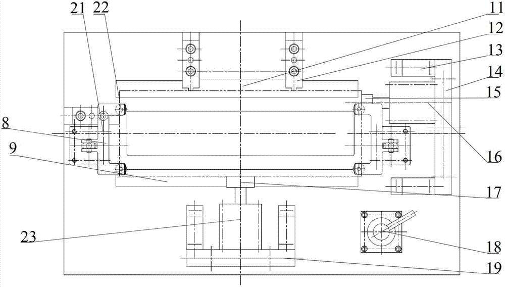
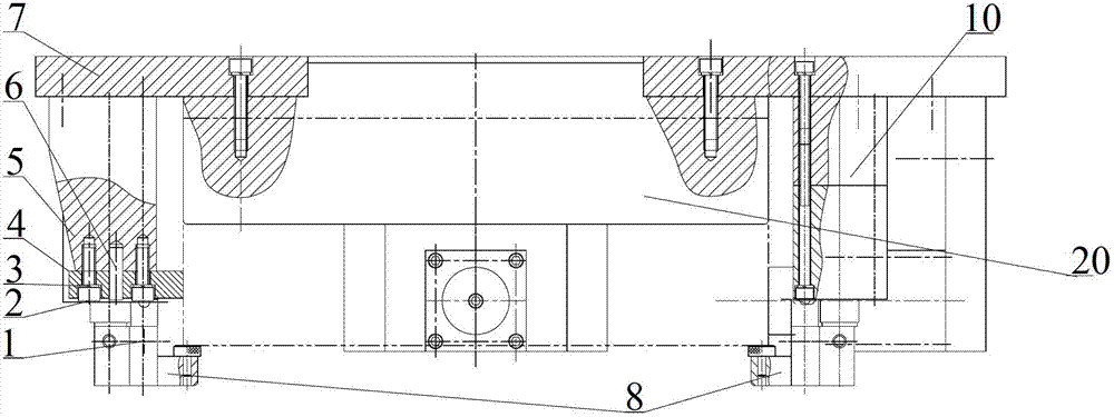
[0019] Such as figure 1 and figure 2 As shown, the horizontal clamping mechanism of the fixture includes an air intake surface support 11 for positioning the air intake surface of the cylinder head 20, an end face support 5 for positioning one end face of the cylinder head 20, and compresses the cylinder head on the other end face of the cylinder head 20. The end face air cylinder 16 of 20 and the exhaust face air cylinder 23 of compressing the cylinder head 20 on the cylinder head 20 exhaust face, the intake face support 11, the end face support 5, the end face air cylinder 16 and the exhaust face air cylinder 23 are fixed on On the base plate 7 , the end face air cylinder 16 and the exhaust face air cylinder 23 are controlled by the air cylinder control device 18 arranged on the base plate 7 . The end face pneumatic cylinder 16 cooperates with the end face support 5 to clamp the cylinder head 20 in one direction of the horizontal plane, and the exhaust face pneumatic cylin...

Embodiment 2

[0022] Such as figure 1 and figure 2 As shown, the intake surface support 11 of the horizontal clamping mechanism is a support plate with the same height as the cylinder head 20 intake surface boss, and the intake surface of the cylinder head 20 is close to the positioning surface of the intake surface support 11 , the positioning surface of the intake surface support 11 will be polished smooth, and the intake surface support 11 is supported and fixed by two intake surface positioning blocks 12 fixed on the base plate 7, and the intake surface support 11 defines a cylinder head 20 Horizontal degrees of freedom.

Embodiment 3

[0024] Such as figure 1 and figure 2 As shown, the end surface support 5 of the horizontal clamping mechanism is positioned against the end surface of the cylinder head 20 by the end surface positioning block 4 arranged thereon, and the positioning surface of one end of the end surface positioning block 4 abuts against the end surface of the cylinder head 20 , the other end is fixed on the end face support 5 by screws 2 (with washers 3 ) and circular positioning pins 6 , the end face positioning block 4 is fastened on the bottom plate 7 , and the end face support 5 defines another horizontal degree of freedom of the cylinder head 20 . The positioning surface of the end face positioning block 4 will be polished smoothly to ensure that the flatness of the positioning surface meets the technical requirements and ensure reliable positioning.


PUM


Abstract

The invention discloses a clamp for processing a positioning hole on an engine cylinder cover. The clamp comprises a base plate for mounting the cylinder cover, a horizontal clamping mechanism used for clamping the cylinder cover in the horizontal direction and arranged on the base plate as well as a vertical clamping mechanism for clamping the cylinder cover in the vertical direction. The horizontal clamping mechanism and the vertical clamping mechanism can be used for clamping the cylinder cover by adopting hydraulic and pneumatic clamping modes. Compared with the prior art, the clamp has the advantages that the cylinder cover is clamped by using a spiral spring pressurizing block in a hydraulic and pneumatic driving and clamping mode instead of a traditional manual operation of workers, so that the cylinder cover is automatically clamped during clamping and further the problem that the efficiency is reduced as the time is consumed for the traditional manual operation in a traditional tooling is greatly reduced and quickness and accuracy in clamping are realized; and in addition, the strength in the hydraulic pressure and air pressure clamping processes can be controlled and the deformation caused by the non-uniformity of the operation strength of workers during clamping is compensated.

Description

technical field [0001] The invention relates to a clamping device, in particular, the invention relates to a clamp used for machining positioning holes of engine cylinder heads. Background technique [0002] At present, during the machining process of the cylinder head of the automobile engine, the machining and clamping of the positioning hole is the first very important process in the process, and the accuracy of the clamping will directly affect the product quality of the cylinder head of the engine, especially for the cylinder head The influence of machining accuracy of other stations. Because the structure of the engine cylinder head is very complicated, the processing technology of the positioning hole is very difficult, the main part of which is the problem of tooling. Generally, when clamping, the cylinder head is placed on two long strips in the machine tool, and then the workers manually Press the cylinder head with a pressure plate with a coil spring, and then st...

Claims


Application Information

Patent Timeline
Patent Type & Authority Applications(China)
IPC IPC(8): B23Q3/00
Inventor 郑志勋
Owner WUHU YONGYU AUTOCAR INDAL
Why Eureka
Try Eureka