Electrode foil conveyer and laminated cell manufacturing device

A technology for transporting devices and stacked batteries, which is applied in the directions of electrode manufacturing, transportation and packaging, and final product manufacturing to achieve the effect of action

Active Publication Date: 2012-10-17
CKD
View PDF6 Cites 4 Cited by
  • Summary
  • Abstract
  • Description
  • Claims
  • Application Information

AI Technical Summary

Problems solved by technology

[0005] However, even when a suction pad is used, if the electrode foils are in close contact with each other, there is a possibility that multiple electrode foils will be lifted up at once.

Method used


Image

  • Electrode foil conveyer and laminated cell manufacturing device
  • Electrode foil conveyer and laminated cell manufacturing device
  • Electrode foil conveyer and laminated cell manufacturing device

Examples


Embodiment Construction

[0058] An embodiment will be described below with reference to the drawings.

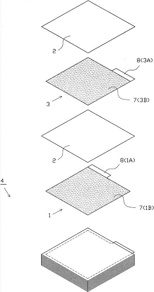
[0059] Such as image 3 As shown, in the laminated body 4 that constitutes the laminated battery, in order from the bottom, the negative electrode foil 1, the separator 2, the positive electrode foil 3, and the separator 2 are repeatedly stacked and stacked (of course, the positive electrode foil can also be stacked). Foil 3 is located on the bottommost layer, on which separator 2, negative electrode foil 1, separator 2, positive electrode foil 3, ... are stacked in this order). As shown in Fig. 4 (a) and Fig. 4 (b), both the negative electrode foil 1 and the positive electrode foil 3 are composed of a planar rectangular part and a protruding part protruding from a part thereof, including an electrode foil main body 1A formed by a metal foil, 3A and the active materials 1B, 3B formed on the inner and outer surfaces of the electrode foil main bodies 1A, 3A are coated. In addition, the electrode foi...


PUM


Abstract

The invention relates to an electrode foil conveyer and a laminated cell manufacturing device. The fault that multiple electrode foils are raised in the electrode foil conveying process can be prevented. Electrode foils (6) are laminated on a stand part (18), and uncoated parts (8) of the electrode foils are arranged on a same side. Firstly, a multilevel bellow sorption pad (36) sorbs and rises the uncoated part (8) of a top electrode foil (6), and then a air-blast nozzle (42) on one side of the uncoated part (8) injects the compressed air, so an end edge of a coated part (7) of the top electrode foil (6) is separated from an end edge of a coated part (7) of a bottom electrode foil (6), and the entire electrode foil (6) rises. The uncoated part (8) which is not tightly pasted and is smaller than the coated part (7) in terms of thickness is preferably lifted. The end edge of the coated part (7) of the top electrode foil (6) can be easily separated from the end edge of the coated part (7) of the bottom electrode foil (6), and only the top electrode foil (6) can be accurately lifted.

Description

technical field [0001] The present invention relates to an electrode foil conveyance device and a laminate battery manufacturing device used in a laminate battery manufacturing process and the like. Background technique [0002] In the manufacturing process of a laminated structure type battery, sheet-shaped positive electrode foils and negative electrode foils are alternately stacked with separators interposed therebetween. The positive electrode foil and the negative electrode foil are each formed by coating an active material on a predetermined metal electrode foil body. In addition, the separator is formed of, for example, an electrically insulating porous resin film. [0003] In the past, these positive and negative electrode foils and separators were laminated by various methods. For example, there is a method in which a plurality of transport devices are provided corresponding to positive electrode foils, negative electrode foils, and separators, and the electrode f...

Claims


Application Information

Patent Timeline
Patent Type & Authority Applications(China)
IPC IPC(8): B65H3/08H01M4/04
CPCY02E60/12Y02E60/10Y02P70/50
Inventor 伊藤史朗
Owner CKD
Why Eureka
Try Eureka