
Oiling-free automobile transmission shaft

A drive shaft, oil-free technology, used in couplings, elastic couplings, mechanical equipment, etc., can solve problems such as drive shaft failure, grease overflow, grease expansion, etc., to increase service life and prevent premature Wear and longevity effect

Inactive Publication Date: 2012-10-17
ZHEJIANG ZHONGLING PRECISION CASTING
View PDF7 Cites 1 Cited by
  • Summary
  • Abstract
  • Description
  • Claims
  • Application Information

AI Technical Summary

Problems solved by technology

The defects and deficiencies of the above technical solutions are: when the transmission shaft is working, due to the repeated high-speed rotation and friction between the shaft head of the cross shaft and the needle roller, and between the needle roller and the inner wall of the bushing, high temperature will be generated in the inner cavity of the bushing. , and the volume of the lubricating grease in the shaft sleeve cavity will expand due to the temperature rise, so that a part of the lubricating grease will overflow out of the shaft sleeve cavity
In this way, over time, the cross shaft and the needle roller will be dry-grinded due to lack of grease, and the drive shaft will still fail

Method used


Image

  • Oiling-free automobile transmission shaft

Examples


Embodiment Construction

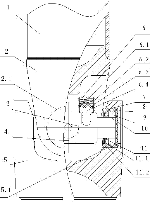
[0013] see figure 1 , the present invention includes shaft tube 1, welding fork 2, welding fork ear hole 2.1, through hole 3, cross shaft 4, flange fork 5, flange fork ear hole 5.1, oil storage device 6, return spring 6.1, piston 6.2, seal Ring 6.3 oil storage chamber 6.4, shaft sleeve 7, snap ring 8, needle roller 9, wear-reducing ring 10, double-lip type circlip 11. Cross shaft 4, flange fork 5, oil seal screw 6, bushing 7, snap ring 8, needle roller 9, wear-reducing ring 10, double-lip circlip 11, circlip inner lip 11.1, circlip outer Lip 11.2 constitutes the universal joint.

[0014] The shaft tube 1 is connected to the welding fork 2 by welding, and the two sides of the welding fork 2 are provided with welding fork ear holes 21 . Both sides of the flange fork 5 are also provided with flange fork ear holes 51, and the axle sleeves 7 of the universal joint are housed in the welding fork ear holes 21 and the flange fork ear holes 51, and the axle sleeves 7 are sleeved on t...


PUM


Abstract

The invention relates to an oiling-free automobile transmission shaft which comprises a shaft tube, a weld yoke, a flange yoke and a universal joint pin. The oiling-free automobile transmission shaft is characterized in that needle rollers are distributed on the inner wall of a shaft sleeve along the circumferential direction; a double-lip elastic retainer ring and a wearing ring are sequentially arranged at one end of the shaft sleeve, which is close to the center of the universal joint pin; the wearing ring is located between the double-lip elastic retainer ring and the needle rollers; an oil storage device is arranged on the universal joint pin; a return spring, a piston and a seal ring are arranged inside the oil storage device; the piston is arranged inside a shell of the oil storage device; the seal ring is arranged at the side face of the circumference of the piston; the return spring is arranged between the piston and the top of the shell of the oil storage device; an oil storage cavity is arranged below the piston; a through hole is arranged inside the universal joint pin; and the through hole is communicated with the inner cavity of the shaft sleeve and the oil storage cavity. The oiling-free automobile transmission shaft is easy to manufacture, low in cost, safe and reliable and has obvious using effect.

Description

technical field [0001] The invention relates to the field of auto parts, in particular to an oil-free auto transmission shaft. Background technique [0002] At present, the transmission shafts on domestic and foreign automobiles often have problems such as card issuance, abnormal noise and early wear during use, and their service life is not long. The reason for the correction is mainly due to the lack of lubricating grease in the inner cavity of the universal joint in the drive shaft, which makes the cross shaft and the needle roller dry-grinded. [0003] The universal joint is an important part in the transmission shaft system, which consists of cross shafts, needle rollers and bushings. The joint between the welded fork and the flanged fork of the propeller shaft. Since the cross shaft in the universal joint can rotate axially with the transmission shaft, it can also rotate radially alternately, so that the transmission shaft can still transfer the power of the engine t...

Claims


Application Information

Patent Timeline
Patent Type & Authority Applications(China)
IPC IPC(8): F16D3/26F16D3/84
Inventor 李立军
Owner ZHEJIANG ZHONGLING PRECISION CASTING
Learn More