Two-way compressing and shearing composite loading test device

A test device and composite loading technology, applied in the direction of measuring device, testing material strength by applying stable shear force, testing material strength by applying stable tension/compression, etc. Stretching and loading devices have complex structures and high costs, and achieve the effect of clear force transmission path, clear force value, and improved stability

Active Publication Date: 2012-10-17
HARBIN INST OF TECH
View PDF5 Cites 26 Cited by
  • Summary
  • Abstract
  • Description
  • Claims
  • Application Information

AI Technical Summary

Problems solved by technology

[0005] The purpose of the present invention is to provide a bidirectional compression shear composite loading test device to solve the problem that the current loading device has a complex structure, high cost and cannot realize the bidirectional tensile or compressive load and in-plane shear load of the reinforced wall plate structure. The compound loading problem

Method used


Image

  • Two-way compressing and shearing composite loading test device
  • Two-way compressing and shearing composite loading test device
  • Two-way compressing and shearing composite loading test device

Examples


specific Embodiment approach 1

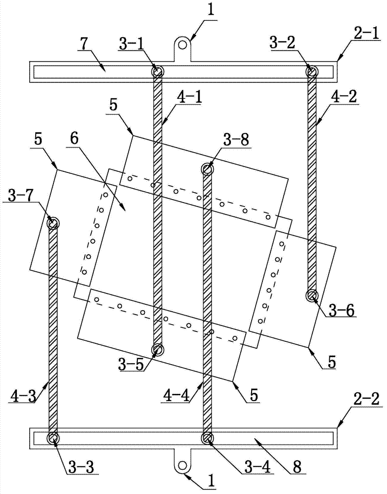
[0009] Specific implementation mode one: combine Figure 1-Figure 4 Describe this embodiment, the two-way compression-shear composite loading test device of this embodiment, the device includes a first distribution beam 2-1 and a second distribution beam 2-2, a first pin 3-1, a second pin 3-2, the third pin 3-3, the fourth pin 3-4, the fifth pin 3-5, the sixth pin 3-6, the seventh pin 3-7, the eighth pin 3- 8. Four pairs of dowel bars and four pairs of loading splints 5, each pair of dowel bars includes two dowel bars arranged in parallel, and the four pairs of dowel bars are respectively defined as the first pair of dowel bars 4-1, the second pair of dowel bars Dowel bars 4-2, the third pair of dowel bars 4-3 and the fourth pair of dowel bars 4-4, the first distribution beam 2-1 and the second distribution beam 2-2 are arranged in parallel, the first distribution beam 2 -1 is provided with the first pin shaft 3-1 and the second pin shaft 3-2, the second distribution beam 2-2...

specific Embodiment approach 2

[0011] Specific implementation mode two: combination figure 1 To illustrate this embodiment, a loading arm 1 is provided at the middle position of the first distribution beam 2-1 and the second distribution beam 2-2 of this embodiment, and this structure is used to connect a testing machine to apply tension. Other implementation manners are the same as the specific implementation manner 1.

specific Embodiment approach 3

[0012] Specific implementation mode three: combination figure 1 To illustrate this embodiment, the first distribution beam 2-1 of this embodiment has a first chute 7, and the first pin shaft 3-1 and the second pin shaft 3-2 slide in the first chute 7; There is a second chute 8 on the two distribution beams 2-2, the third pin 3-3 and the fourth pin 3-4 slide in the second chute 8, this structure can adjust the first pin 3- 1. The positions of the second pin shaft 3-2, the third pin shaft 3-3 and the fourth pin shaft 3-4 on the distribution beam. Other implementation manners are the same as the specific implementation manner 1.

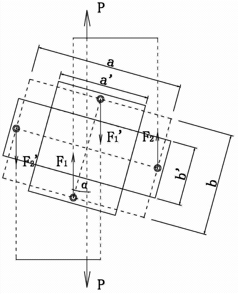
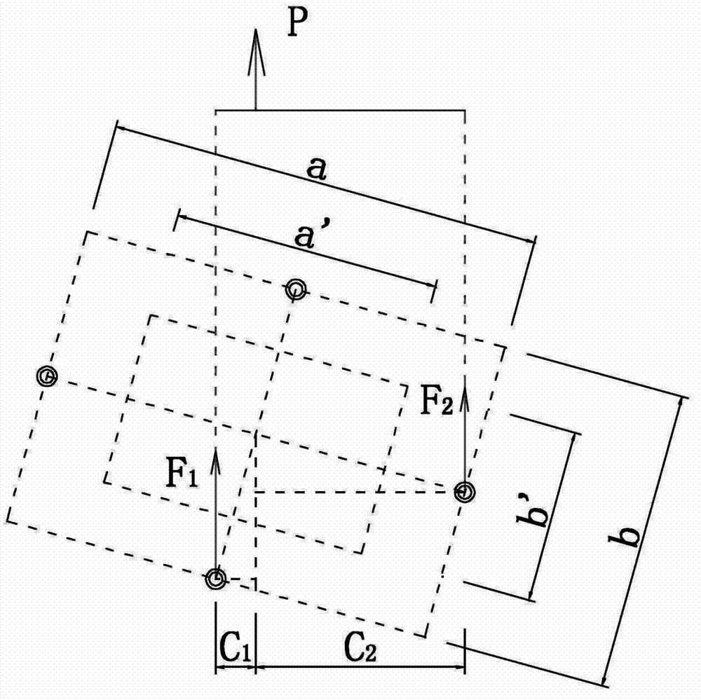
[0013] How it works: combined Figure 2-Figure 4 Explain the principle of the bidirectional compression-shear composite loading test device, the tensile force P of the testing machine, the deflection angle α of the test piece (that is, the connection line between the center of the fifth pin shaft 3-5 and the center of the eighth pin shaft 3-8 and the ...


PUM


Abstract

The invention discloses a two-way compressing and shearing composite loading test device and relates to a composite loading test device. The device is to solve the problems that the existing loading device is complicated in structure and high in cost, and cannot achieve composite loading of two-way stretching or compressing load and inside shearing load of a reinforced wall plate structure. A first distributing girder and a second distributing girder are arranged in parallel; a first pin shaft and a second pin shaft are arranged on the first distributing girder; a third pin shaft and a fourth pin shaft are arranged on the second distributing girder; four pairs of loading clamp plates and a test piece are arranged between the first distributing girder and the second distributing girder; four edges of the test piece are detachably connected through the four pairs of loading clamp plates; a first pair of dowel steels are rotationally connected through the first pin shaft and a fifth pin shaft; a second pair of dowel steels are rotationally connected through the second pin shaft and a sixth pin shaft; a third pair of dowel steels are rotationally connected through the third pin shaft and a seventh pin shaft, and a fourth pairs of dowel steels are rotationally connected through the fourth pin shaft and an eighth pin shaft. The two-way compressing and shearing composite loading test device is used for a composite loading test of a reinforced wall plate structure component for aerospace.

Description

technical field [0001] The invention relates to a compound loading test device. Background technique [0002] Reinforced wall panels in aerospace engineering structures are a basic structural component that can withstand in-plane tensile, compressive, and shear loads, and have a wide range of applications. During service, this type of structure bears unidirectional or bidirectional tensile and compressive loads, as well as in-plane shear loads. [0003] When designing such structures, it is often necessary to verify the bearing capacity and stability through experiments. Since applying tensile shear or compressive shear loads on the test piece requires complex loading devices and high test conditions, the simplified method is to do a separate in-plane shear test and uniaxial tension-compression test on the test piece. Since the most unfavorable condition of the stiffened panel during service is to bear the combined action of in-plane axial compression and shear loads, in o...

Claims


Application Information

Patent Timeline
Patent Type & Authority Applications(China)
IPC IPC(8): G01N3/08G01N3/24G01N3/02
Inventor 程翔高维成刘伟马胜强李小乐
Owner HARBIN INST OF TECH
Why Eureka
Try Eureka