
Solar cell assembly

A technology of solar cells and components, applied in electrical components, circuits, photovoltaic power generation, etc., can solve the problems of increasing the demand for welding strips and increasing labor intensity, and achieve the effect of reducing welding labor intensity and saving costs

Inactive Publication Date: 2012-10-17
JIANGSU SINSKI PV
View PDF2 Cites 0 Cited by
  • Summary
  • Abstract
  • Description
  • Claims
  • Application Information

AI Technical Summary

Problems solved by technology

[0002] The battery sheets used in conventional solar cell modules need to weld the main and auxiliary grid lines on the front side when they are connected in series, which increases the labor intensity and also increases the demand for welding strips.

Method used


Image

  • Solar cell assembly
  • Solar cell assembly
  • Solar cell assembly

Examples


Embodiment Construction

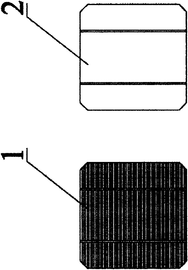
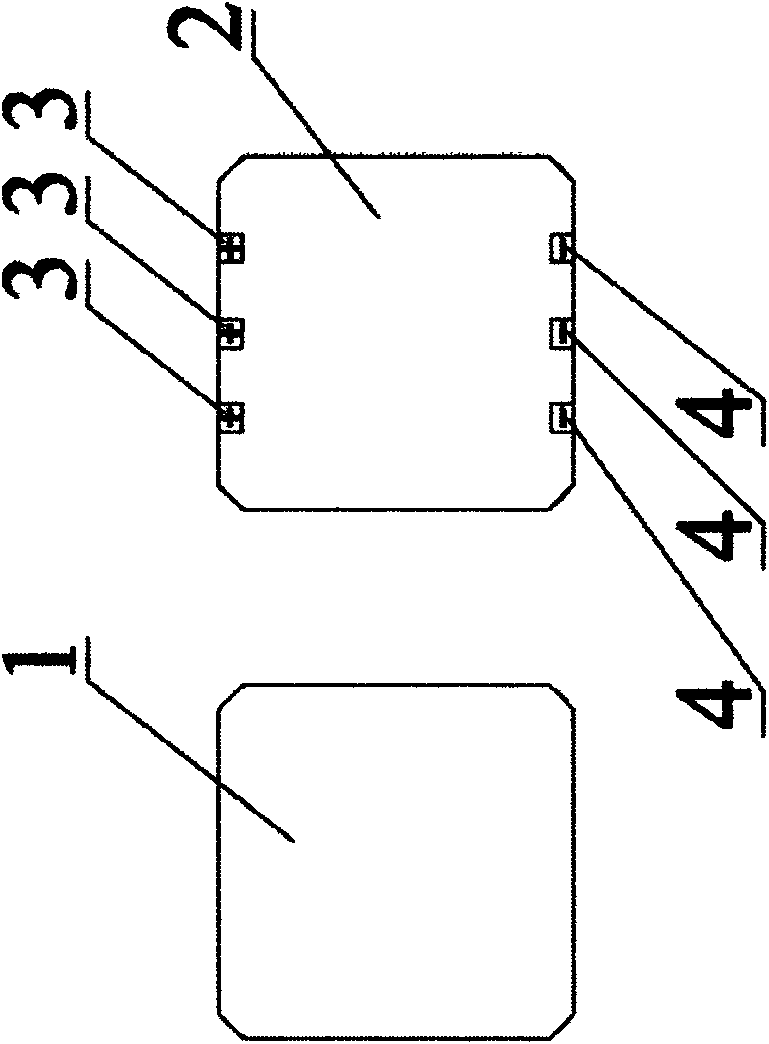
[0013] Such as figure 1 , figure 2 , image 3 and Figure 4 As shown, a solar cell assembly of the present invention is formed by connecting a plurality of battery sheets in series. The front side 1 of the battery sheet has no main and auxiliary grid lines, and the back side 2 of the battery sheet is processed with positive electrode solder joints 3 , corresponding to The corresponding other side is processed with a negative electrode solder joint 4 .

[0014] The positive electrode solder joints 3 and the negative electrode solder joints 4 on the back of adjacent battery sheets are welded together.


PUM


Abstract

Disclosed in the invention is a solar cell assembly formed by a plurality of cell slices in series connection. There are no main and auxiliary gate lines at the right sides of the cell slices; positive electrode welding points are processed at one side edges of the back sides of the cell slices and negative electrode welding points are processed at the other corresponding side edges; and the positive electrode welding points and the negative electrode welding points at the back sides of the adjacent cell slices are welded together. According to the invention, the provided solar cell assembly is beautiful; and the welding labor intensity is reduced and the cost is saved.

Description

technical field [0001] The invention relates to a battery assembly, in particular to a solar battery assembly. Background technique [0002] The battery sheets used in conventional solar cell modules need to weld the main and auxiliary grid lines on the front side when they are connected in series, which increases the labor intensity and also increases the demand for welding strips. Contents of the invention [0003] The problem to be solved by the present invention is to overcome the deficiencies in the background technology and provide a solar cell module. This solar cell module uses cells with no main and auxiliary grid lines on the front, which is not only beautiful, but also reduces the labor intensity of welding and saves costs. . [0004] In order to solve the above problems, the present invention takes the following technical solutions: [0005] A solar battery module of the present invention is composed of a plurality of battery slices connected in series. There...

Claims


Application Information

Patent Timeline
Patent Type & Authority Applications(China)
IPC IPC(8): H01L31/05H01L31/042
CPCY02E10/50
Inventor 卢守杰
Owner JIANGSU SINSKI PV
Learn More