Unlock instant, AI-driven research and patent intelligence for your innovation.

Direct grid-tied variable-speed constant-frequency generator

A main generator, generator rotor technology, applied in electrical components, electromechanical devices, etc., can solve the problems of high cost, high failure rate, complex production and assembly process, etc., to achieve improved power quality, reduced failure rate, and compact structure. Effect

Inactive Publication Date: 2012-10-17
王光顺
View PDF5 Cites 5 Cited by
  • Summary
  • Abstract
  • Description
  • Claims
  • Application Information

AI Technical Summary

Problems solved by technology

However, this direct grid-connected variable speed constant frequency generator uses a large number of hollow shafts and brushes, the production and assembly process is complicated, the cost is high, and the failure rate is high

Method used


Image

  • Direct grid-tied variable-speed constant-frequency generator
  • Direct grid-tied variable-speed constant-frequency generator

Examples


Embodiment Construction

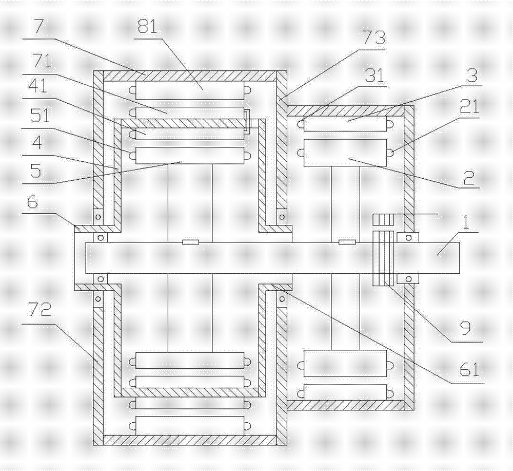
[0016] Such as figure 1 As shown, the direct grid-connected variable speed constant frequency generator of the present invention includes a main shaft 1, a generator rotor 2 fixedly mounted on the main shaft 1, and a generator stator 3 arranged around the generator rotor 2 to generate electricity The generator rotor 2 is equipped with a generator DC excitation coil 21, the generator stator 3 is equipped with a generator armature coil 31, the generator stator 3 is installed on the main shaft 1 through a bearing, and the generator rotor 2 is fixedly installed on the main shaft 1 to generate electricity. The stator 3 and the rotor 2 of the generator form an air gap fit.

[0017] A generator exciter is also installed on the main shaft 1. The generator exciter includes an exciter armature 4 mounted on the main shaft 1 through a bearing, an exciter rotor 5 fixedly mounted on the main shaft 1, and an exciter rotor 5 The DC excitation coil 51 of the exciter rotor is fixedly installed on ...


PUM


Abstract

The invention relates to a generator, and particularly relates to a direct grid-tied variable-speed constant-frequency generator. The generator comprises a main shaft, a generator rotor fixedly arranged on the main shaft and a generator stator which is arranged on the periphery of the generator rotor in a surrounding manner, wherein the generator rotor is provided with a generator direct current excitation coil, and the generator stator is provided with a generator armature coil; the generator stator is arranged on the main shaft through a bearing, and the generator rotor is fixedly arranged on the main shaft; an exciter is arranged on the main shaft and comprises an exciter armature shell arranged on the main shaft and an exciter rotor fixedly arranged on the main shaft; the exciter rotor is fixedly provided with an exciter rotor direct current excitation coil; the inner side wall of the exciter armature shell is fixedly provided with an exciter armature, and the outer side wall of the exciter armature is fixedly provided with a main generator rotor winding coil; a main generator armature shell is sleeved on the outer side of the exciter armature shell and is fixedly connected with the generator stator; and the inner side wall of the main generator armature shell is fixedly provided with a main generator stator coil. When the rotating speed of the generator changes, the output voltage frequency of the generator and network frequency are kept same all the time; and the generator disclosed by the invention is compact in structure and simple in production process.

Description

Technical field [0001] The invention relates to a generator, in particular to a direct grid-connected variable speed constant frequency generator. Background technique [0002] In order to meet the requirements of grid-connected power generation by wind turbines and other variable-speed generators, the output voltage frequency needs to be consistent with the grid frequency at different speeds. Now direct-drive generators, doubly-fed generators, etc. mainly use rectification— The inverter method electronically adjusts the output frequency. Due to the complex structure, high failure rate and high cost of the inverter, it has become a major obstacle to the grid-connected power generation of variable-speed generators such as wind power. My other patent application "Direct grid-connected variable speed constant frequency generator", application number 2011204233619, discloses a feedback frequency modulated generator including a main generator, an exciter, and a main generator. The mai...

Claims


Application Information

Patent Timeline
IPC IPC(8): H02K16/00
CPCH02K16/00
Inventor 王光顺王雪霖
Owner 王光顺
Features
  • R&D
  • Intellectual Property
  • Life Sciences
  • Materials
  • Tech Scout
  • Unparalleled Data Quality
  • Higher Quality Content
  • 60% Fewer Hallucinations
Learn More