Supercharge Your Innovation With Domain-Expert AI Agents!

Method and system for logic signal synchronization and synthesis

A logic signal and logic technology, applied in the field of logic signal synchronization and synthesis, can solve the problem of high cost

Active Publication Date: 2014-12-10
VERTIV CORP
View PDF5 Cites 0 Cited by
  • Summary
  • Abstract
  • Description
  • Claims
  • Application Information

AI Technical Summary

Problems solved by technology

However, the hardware of logic signals involves signal synchronization issues, and usually requires complex logic programmable gate arrays (CPLD or FPGA) to implement
Complex hardware system causes high cost

Method used


Image

  • Method and system for logic signal synchronization and synthesis
  • Method and system for logic signal synchronization and synthesis
  • Method and system for logic signal synchronization and synthesis

Examples


Embodiment Construction

[0054] In order to enable those skilled in the art to better understand and implement the present invention, several technical terms are firstly introduced below.

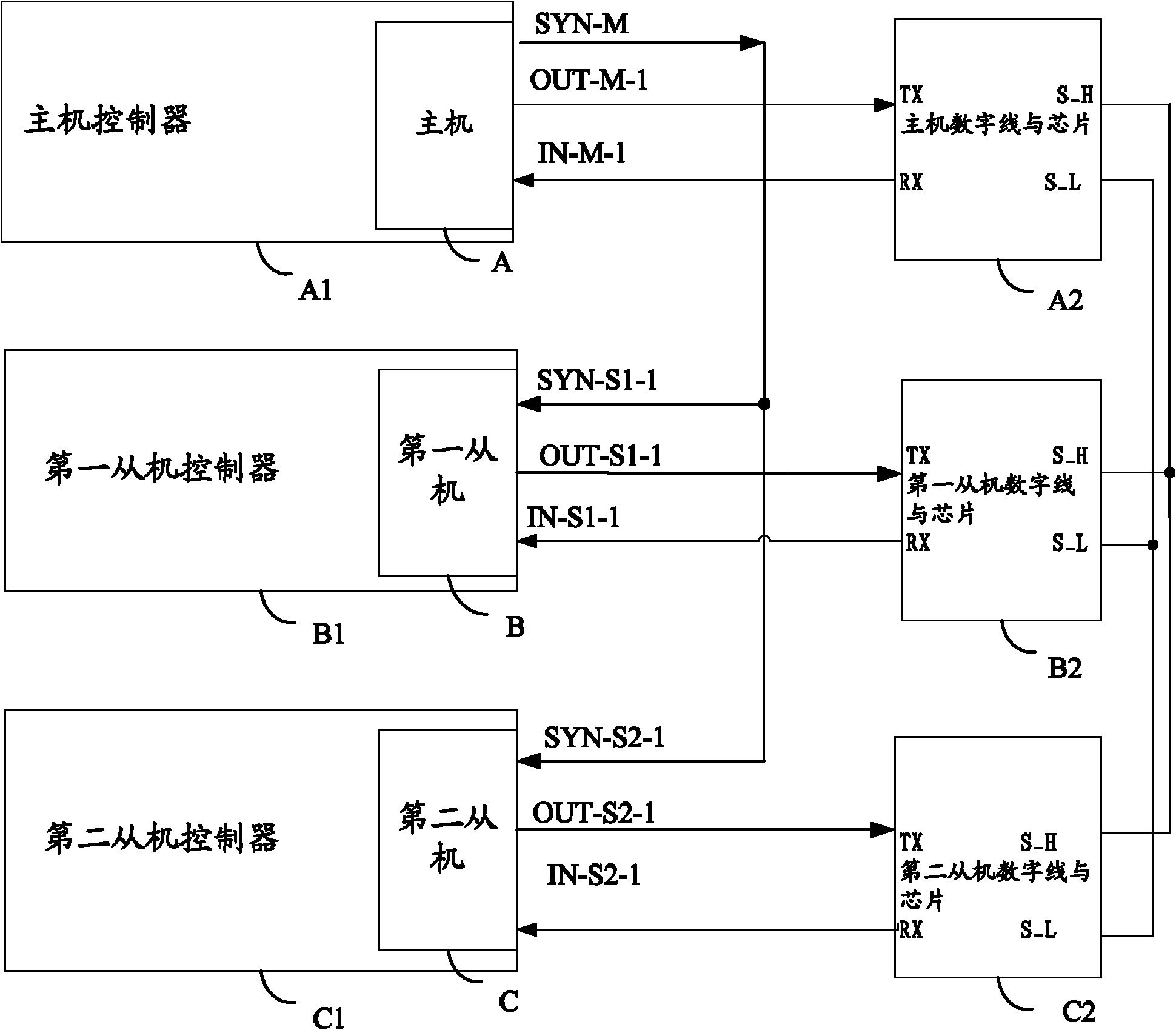
[0055] A parallel system refers to a system in which multiple members are connected in parallel, one of which is the master and the other members are slaves.

[0056] The redundancy of the logic signal means that there are two channels for the transmission of the logic signal in the parallel system, and the two channels serve as backups for each other.

[0057] In order to make the above objects, features and advantages of the present invention more comprehensible, specific implementations of the present invention will be described in detail below in conjunction with the accompanying drawings.

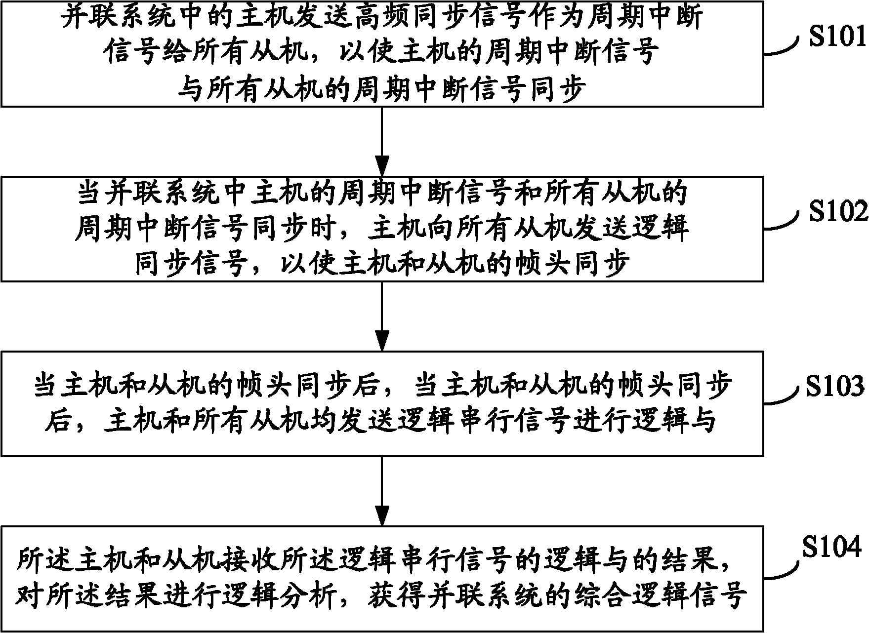
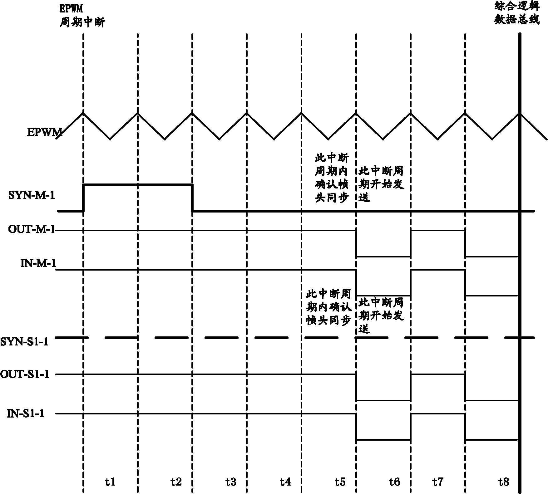
[0058] see figure 1 , which is a flow chart of Embodiment 1 of a method for synchronizing and synthesizing logic signals in an uninterruptible power supply provided by the present invention.

[0059] The method for synchr...


PUM


Abstract

The invention provides a method and a system for logic signal synchronization and synthesis. The method comprises the steps: firstly, interrupt signals of all members in a parallel system are synchronized by using periodic interrupt signals of a host; and then, logical serial signals are transmitted to all slaves by using the host and frame headers of all the members are synchronized under interrupt signal synchronization; and finally, all the members receive and transmit logic signals synchronously under the premise of interrupt signal and frame header synchronization, thus realizing synchronization of logic signals in the parallel system. Instead of using either a CAN bus or a complex hardware programmable logic gate array, the method for logic signal synchronization provided by the invention uses resource of the parallel system itself as well as simple wires and / or chips to realize synchronization of logic signals in the whole system, and thus instantaneity of the system can be guaranteed and cost can be reduced.

Description

technical field [0001] The invention relates to the technical field of inverter control, in particular to a logic signal synchronization and synthesis method and system. Background technique [0002] An uninterruptible power supply (UPS, uninterruptible power system) is used to provide an uninterruptible power supply for the system when the system is powered off. UPS is mainly composed of several parts such as rectifier, battery, inverter and static switch. [0003] In order to increase the load capacity of the UPS, the AC output ends of multiple inverters are often connected in parallel to supply power to the load. If one of the inverters or other modules fails, other normal modules connected in parallel can continue to work to supply power to the load. [0004] Since the inverters are connected in parallel to supply power to the load, the behavior of each inverter in parallel needs to be consistent. The consistency of this behavior is mainly in two aspects: first, the l...

Claims


Application Information

Patent Timeline
Patent Type & Authority Patents(China)
IPC IPC(8): H04L7/00
Inventor 李德军
Owner VERTIV CORP
Features
  • R&D
  • Intellectual Property
  • Life Sciences
  • Materials
  • Tech Scout
  • Unparalleled Data Quality
  • Higher Quality Content
  • 60% Fewer Hallucinations
Learn More