
Chain link, conveyor element, and device for compressing tobacco, ribs, or the like

A technology of conveying elements and strips, which is applied in the field of chain links, can solve the problems of conveyor chain wear, wrong orientation, and guide conveyor chains, and achieve the effects of small tolerance requirements, cost reduction, and reliable guidance

Inactive Publication Date: 2012-10-17
HAUNI MASCHINENBAU AG
View PDF10 Cites 2 Cited by
  • Summary
  • Abstract
  • Description
  • Claims
  • Application Information

AI Technical Summary

Problems solved by technology

The problem with driving conveyor chains is that the conveyor chain or the individual links forming the conveyor chain, usually made of brass, deviate transversely to the conveying direction F, ie towards the side wall of the compression chamber, and thus lead to Frictional connection between side walls, usually made of stainless steel
However, it has been found that centering with this centering spacer is not sufficient for guiding the conveyor chain over the entire conveyor path
In other words, known conveyor chains also wear very quickly, which leads to considerable costs when repairing and / or replacing the conveyor chain or individual chain links
In addition, the wear and wrong orientation of the conveyor chain also lead to: the tobacco throughput on the side edges is very significant

Method used


Image

  • Chain link, conveyor element, and device for compressing tobacco, ribs, or the like
  • Chain link, conveyor element, and device for compressing tobacco, ribs, or the like
  • Chain link, conveyor element, and device for compressing tobacco, ribs, or the like

Examples


Embodiment Construction

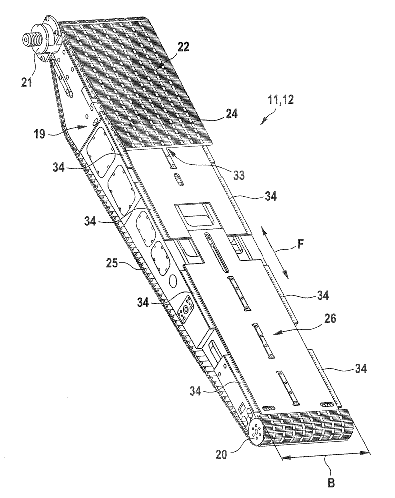
[0025] The device and parts of the device shown in the figures are used for compressing tobacco, rods or the like. The parts of the device, in particular the chain links and the conveying elements, are designed and arranged to form a conveying chain for such a device or to convey tobacco, rods or the like in such a device.

[0026] figure 1 The device 10 shown in for compressing tobacco, rods or the like comprises two conveying elements 11 , 12 . The two delivery elements 11 , 12 are arranged one above the other and each form a compression element. The two conveying elements 11 , 12 are arranged tapering toward the nozzle 13 , so that the tobacco or the like conveyed in the conveying direction F is compressed into a tobacco cake and cut into small pieces in the region of the cutting surface S. The conveying elements 11 , 12 can optionally be designed to be fixed relative to each other or to be movable towards or away from each other. However, a distance change and / or a chan...


PUM


Abstract

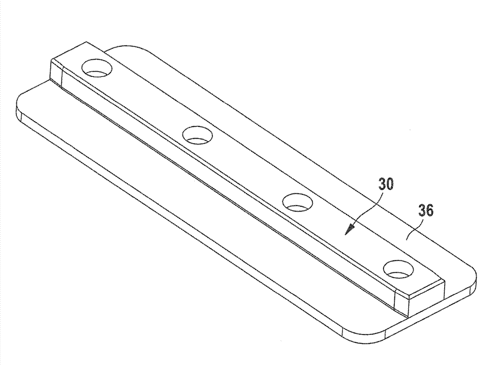
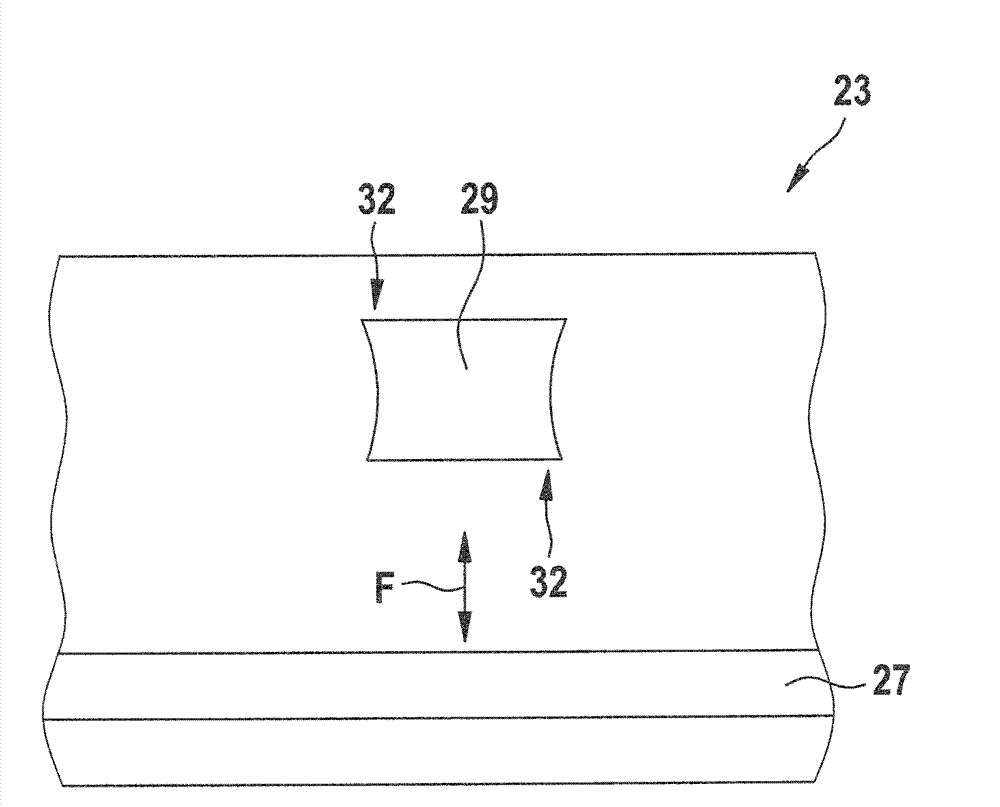
The invention relates to a chain link (23), designed and set up for forming a conveyor chain for a device for compressing tobacco, ribs, or the like, having a upper face (O) forming the transport surface and an opposite lower face (U), and a groove (27) extending over the entire width (B) of the chain link (23), and a protrusion (28) extending over the entire width (B) of the chain link (23), the groove (27) and the protrusion (28) being adapted in form for a form-fit connection to other chain links (23) of corresponding design, characterized in that the chain link (23) comprises a continuous recess (29) in the conveying direction on the lower face (U) that can be brought into engagement with a corresponding ridge of a slide plate of the device.

Description

technical field [0001] The invention relates to a chain link designed and arranged to form a conveyor chain for devices for compressing tobacco, rods or the like, the chain link having: an upper side forming a conveyor surface; and Opposite undersides; and grooves extending over the entire width of the chain link; and projections extending over the entire width of the chain link, wherein the grooves and projections are structurally adapted to other The chain links are positively connected. [0002] In addition, the present invention relates to a conveying element designed and arranged for conveying tobacco, rods or the like in a device for compressing tobacco, rods or the like, the conveying element comprising: a frame; a plurality of supports Guide rollers and / or drive rollers for a conveyor chain on a frame; a continuously running conveyor chain guided around guide rollers and / or drive rollers, which conveyor chain consists of form-fittingly interconnected chain links, wher...

Claims


Application Information

Patent Timeline
IPC IPC(8): B65G17/08B65G21/22A24B7/14
CPCA24B7/14B65G17/08B65G21/22
Inventor U.鲍施
Owner HAUNI MASCHINENBAU AG
Learn More