Lock assembly and safe applying same
A technology for a lock assembly and a safe is applied in the field of a lock assembly and a safe using the lock assembly to achieve the effects of improving safety performance, improving insurance performance and preventing violent damage
- Summary
- Abstract
- Description
- Claims
- Application Information
AI Technical Summary
Problems solved by technology
Method used
Image
Examples
Embodiment 1
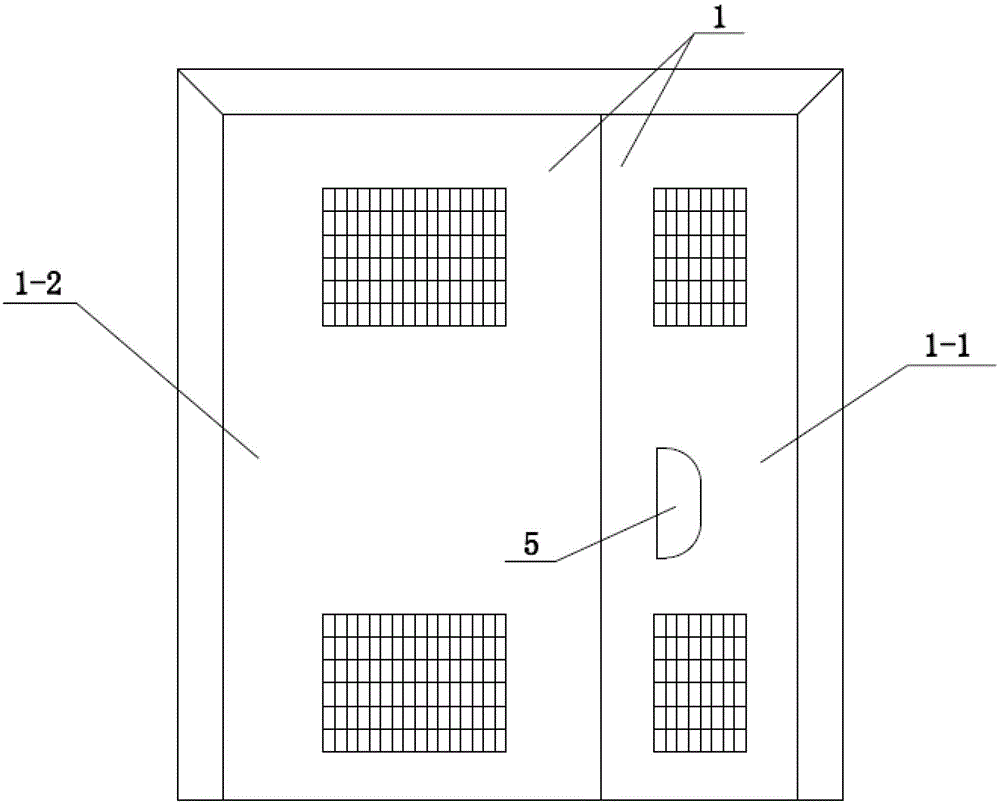
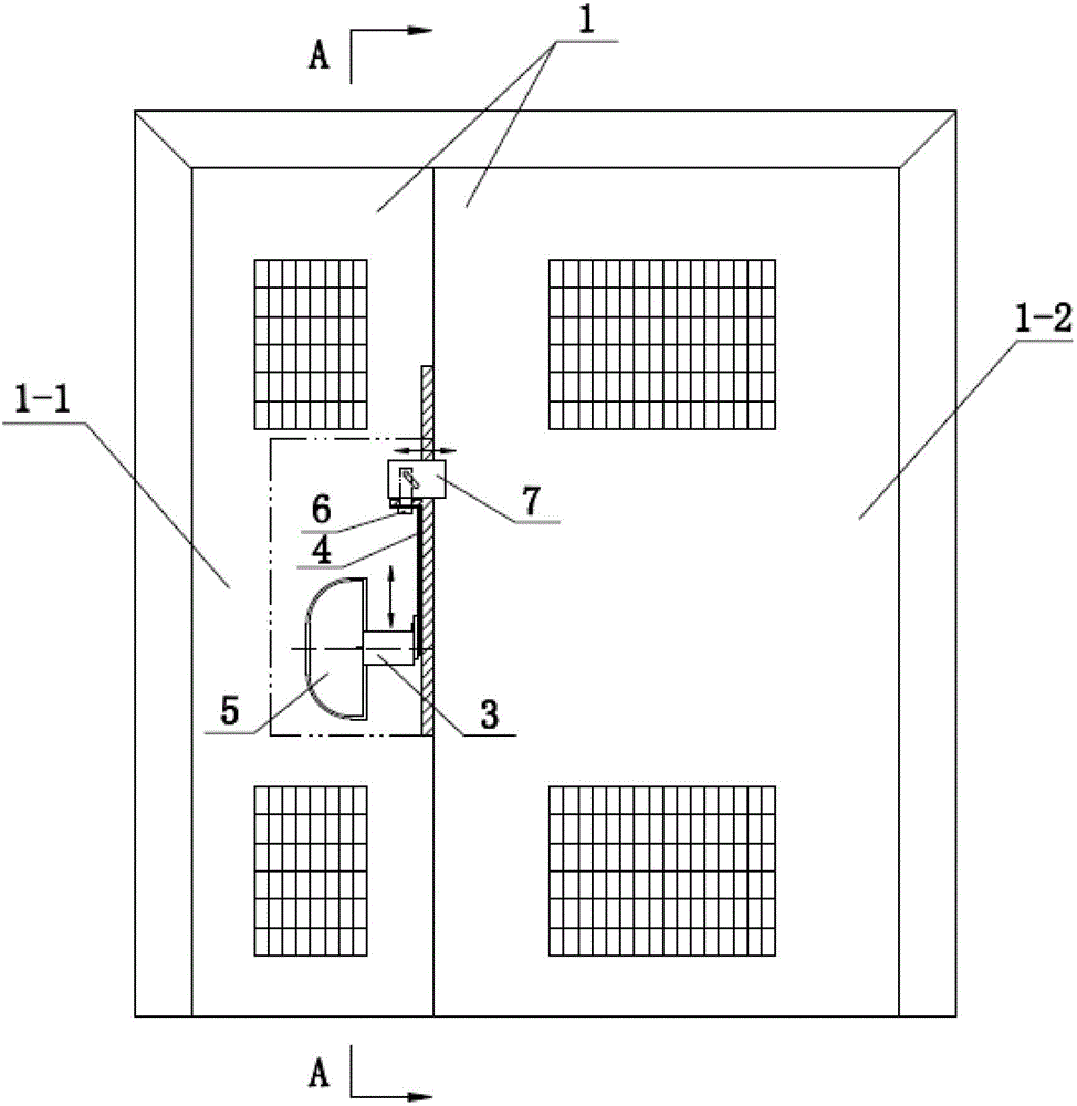
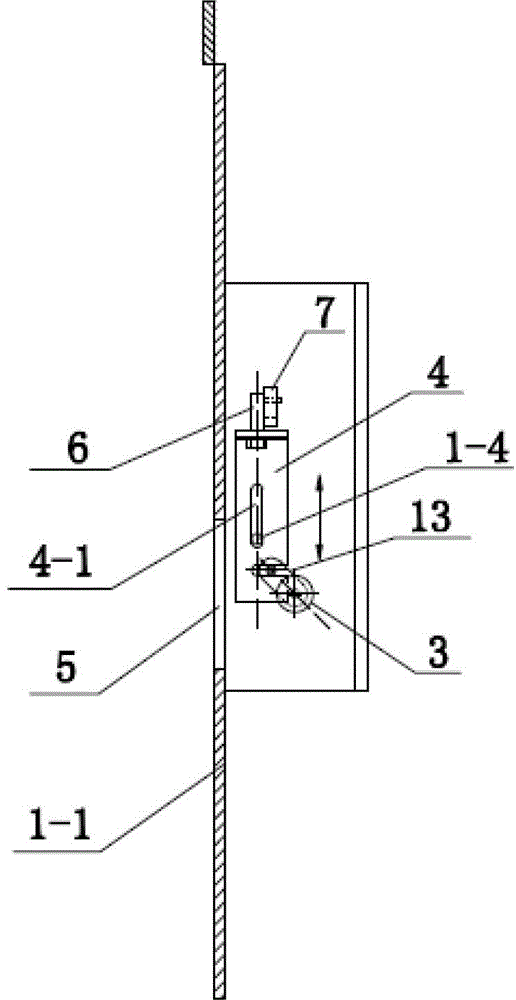
[0026] See Figure 1 ~ Figure 5 , The figure shows a structure of the lock assembly of the present invention used on a stainless steel door 1, wherein the stainless steel door 1 is composed of a door leaf 1-2 and a small door leaf 1-1; the lock assembly includes a lock core 3 And bolting mechanism, wherein the lock core 3 is arranged inside the small door leaf 1-1 (ie the first wall), and its axis is horizontal and parallel to the surface of the small door leaf 1-1, and the key hole end face of the lock core 3 faces Inside the door frame (ie, the second wall) of the small door leaf 1-1, the small door leaf 1-1 is provided with a vertical depression formed by the surface of the small door leaf 1-1 at the end face of the key opening close to the lock cylinder 3. The unlocking space 5 has a width equivalent to the length of the key 12, and the end face of the key port of the lock core 3 is located in the unlocking space 5. The bolting mechanism is composed of a lock rod 4 and a sli...
Embodiment 2
[0029] See Figure 6 ~ Figure 9 , The figure shows another structure in which the lock assembly of the present invention is applied to a stainless steel door 1. Among them, the stainless steel door 1 is the same as the stainless steel door 1 corresponding to embodiment 1, and consists of the door page 1-2 and the small door page 1- 1 composition; the lock assembly of this embodiment adds a main lock on the basis of embodiment 1, using the main lock to replace the sliding bolt 7 in embodiment 1, wherein the upper end of the lock rod 4 is provided with a cylindrical plunger 8 to replace the push-pull rod 6 in embodiment 1; the main lock is arranged on the inner side of the door leaf 1-2, the main lock is composed of the main lock core 9, the sliding bracket 10 and the lock bolt 11, wherein the main lock core 9 is set in On the door leaf 1-2, the axis is perpendicular to the door surface, and the sliding bracket 10 is arranged horizontally. One end is connected with the crank 13 on...
Embodiment 3
[0032] See Figure 10 ~ Figure 13 The safe of the present invention includes a box body 14 and a box door 15, wherein the box body 14 has a double-layer structure, and the front of the box body 14 occupies most of the area as the box door 15, and the one that occupies a smaller area is joined with the box door 15 The part of is the lock panel 16 for setting the lock core 3, and the handle 2 is provided on the box door 15. The safe is provided with the lock assembly of the present invention and an electric control lock 17, wherein the lock assembly includes a lock core 3, a bolting mechanism and a main lock. The lock cylinder 3 and the bolting mechanism are arranged in the lock installation space 18 enclosed by the steel plate on the inner side of the lock installation panel 16 (that is, the first wall). The lock cylinder 3 is horizontally arranged in the lock installation space 18, and the lock The axis of the core 3 is horizontal and parallel to the surface of the lock panel 1...
PUM
 Abstract
Description
Claims
Application Information
 - R&D
- Intellectual Property
- Life Sciences
- Materials
- Tech Scout
- Unparalleled Data Quality
- Higher Quality Content
- 60% Fewer Hallucinations
Browse by: Latest US Patents, China's latest patents, Technical Efficacy Thesaurus, Application Domain, Technology Topic, Popular Technical Reports.
© 2025 PatSnap. All rights reserved.Legal|Privacy policy|Modern Slavery Act Transparency Statement|Sitemap|About US| Contact US: help@patsnap.com


