
Well drilling vibrator of horizontal well

A technology of horizontal wells and vibrators, which is applied in vibratory drilling, wellbore/well components, earthwork drilling and production, etc. It can solve the problems of limited drilling footage in the horizontal section, poor ability to transmit drilling pressure, and difficulty in running coiled tubing. It achieves the effect of increasing the ROP, strong axial vibration ability and increasing the uniform contact time

Inactive Publication Date: 2012-10-24
CHINA PETROLEUM & CHEM CORP +1
View PDF6 Cites 24 Cited by
  • Summary
  • Abstract
  • Description
  • Claims
  • Application Information

AI Technical Summary

Problems solved by technology

More than 7,000 wells are drilled with coiled tubing in the world, and the application is becoming more and more extensive; as the length of coiled tubing increases in the horizontal well section, the friction between coiled tubing and the well wall increases. Due to the poor pressure capacity, the drilling footage of the horizontal section is limited, and the horizontal driving force generated by the surface injection head alone cannot make the coiled tubing reach the expected depth. The difficulty of running the coiled tubing in the horizontal well section also restricts its development. one of the main factors of

Method used


Image

  • Well drilling vibrator of horizontal well
  • Well drilling vibrator of horizontal well
  • Well drilling vibrator of horizontal well

Examples


Embodiment Construction

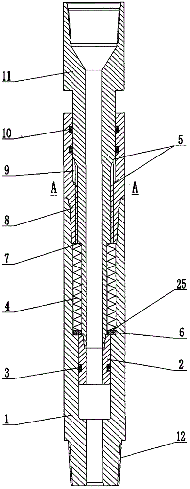
[0015] Below in conjunction with accompanying drawing, the present invention will be further described, as Figure 1-Figure 6 Shown; a horizontal well drilling vibrator, its structure is made up of an oscillating part and a valve part; the oscillating part is mainly composed of a housing (1), a piston head (2), a lower sealing ring (3), a disc spring (4) , support end face (5), spacer (6), upper shoulder (7), static sleeve (8), sliding cavity (9), upper sealing ring (10), sliding shaft (11), housing male thread ( 12) and lower shoulder (25) form. The valve parts are mainly composed of valve housing (13), retaining ring (14), spring (15), center pipe (16), sliding valve body (17), nozzle (18), water eye (19), second flow channel (20), valve plug (21), first flow passage (22), fixed valve seat (23) and housing female screw thread (24). The housing (1) of the oscillating part is connected with the static sleeve (8) by threads, and the sliding shaft (11) is installed in the cent...


PUM


Abstract

The invention relates to a well drilling vibrator of a horizontal well. The well drilling vibrator comprises a shell, a piston head, a disc spring, an upper shoulder, a fixed sleeve, a sliding shaft, a valve shell, a spring, a central pipe, a sliding valve body, a nozzle, a water hole, a second flow passage, a valve plug, a first flow passage and a fixed valve seat, wherein the shell is in threaded connection with the fixed sleeve; the sliding shaft is arranged in a central hole formed by the shell and the fixed sleeve; the fixed sleeve is matched with the sliding shaft through a spline; the fixed valve seat is fixedly arranged in the valve shell through thread; the valve plug is matched with the fixed valve seat; when water pressure at the upper end of the valve plug reaches a limited value, the valve plug is separated from the fixed valve seat, the spring is compressed downwards by the central pipe, and drilling fluid flows by the first flow passage and then flows by the second flow passage; when pump capacity changes, the water pressure at the upper end of the valve plug also changes, the compression of the spring changes, the distance from the valve plug to the fixed valve seat changes, the flow area of the first flow passage also changes, and pulsating pressure is caused to change the compression amplitude of the disc spring by the upper shoulder of the sliding shaft, so that vibration is caused.

Description

technical field [0001] The invention relates to a horizontal well drilling tool for petroleum drilling, in particular to a horizontal well drilling vibrator used for improving the extended drilling ability of the horizontal section in the drilling of directional wells, horizontal wells and extended displacement wells. Background technique [0002] At present, with the deepening of oilfield exploration and development, the proportion of directional wells, horizontal wells and extended reach wells is increasing. Long horizontal section drilling technology has been widely used at home and abroad, mainly due to its good input-output ratio. In the drilling process of horizontal wells and extended-reach wells, due to high frictional resistance, the drilling efficiency is low, the drilling cycle is long, and the drilling cost is high, which has become the main bottleneck restricting the development of horizontal wells and extended-reach wells. In field practice, due to too much fr...

Claims


Application Information

Patent Timeline
IPC IPC(8): E21B28/00E21B7/24
Inventor 郝荣明苏山林张国伟王鑫徐建飞祝效华石昌帅童华张鹏任广兵刘光磊冯相尧张中伟
Owner CHINA PETROLEUM & CHEM CORP
Learn More