
Device for reducing friction between drilling tool and well wall and method thereof

A wellbore and drilling tool technology, which is applied to the device and its field for reducing the friction between the drilling tool and the wellbore, can solve the problems that the drilling tool cannot be lifted or the drill is broken, the coiled tubing is reached, and the softness is hit. Improve the uniform contact time, strong axial vibration ability, and improve the effect of control accuracy

Active Publication Date: 2020-02-04
SOUTHWEST PETROLEUM UNIV
View PDF5 Cites 3 Cited by
  • Summary
  • Abstract
  • Description
  • Claims
  • Application Information

AI Technical Summary

Problems solved by technology

[0002] With the continuous increase of human demand for oil resources and the continuous reduction of oil and gas resources around the world, in order to meet human needs for oil resources, complex oil and gas reservoirs such as low permeability, low pressure and low porosity have been developed. Directional wells, extended-reach wells and horizontal wells are also more and more widely used; at present, with the continuous progress of oil and gas reservoir exploration and development technology, the proportion of directional wells, horizontal wells and extended-reach wells in oil and gas reservoir exploration and development In the drilling process of directional wells, extended reach wells and horizontal wells, due to the high frictional resistance between the drilling tool and the well wall, the drilling efficiency is low, the drilling cycle is long, the drilling cost is high, and the ROP The wellbore trajectory fails to meet the design requirements, the target formation rate is low, and sometimes accidents such as inability to lift the drilling tool or breakage of the drill occur. This has become one of the important bottlenecks restricting the development of directional wells, extended-reach wells and horizontal wells. one
[0003] Coiled tubing technology is an economical and environmentally friendly operation method. This technology has great advantages in operations such as well washing, salvage, horizontal wells, extended-reach wells, and sidetracking of existing wells. , One of the leading technologies for mining difficult-to-use reserves and enhancing ultimate recovery; since the 1990s, more than 7,000 wells have been drilled with coiled tubing in the world, and the annual increase is 750 ~ At the same time, with the increase in the number of horizontal wells, the length of the coiled tubing in the horizontal well increases, and the friction between the coiled tubing and the well wall increases. Due to the small size of the coiled tubing and its softness, Poor ability to transmit drilling pressure results in limited drilling footage in the horizontal section. The horizontal driving force generated by the surface injection head alone often cannot make the coiled tubing reach the expected depth. The difficulty of running the coiled tubing in the horizontal well section also becomes a constraint one of the main factors in its development

Method used


Image

  • Device for reducing friction between drilling tool and well wall and method thereof
  • Device for reducing friction between drilling tool and well wall and method thereof
  • Device for reducing friction between drilling tool and well wall and method thereof

Examples


Embodiment Construction

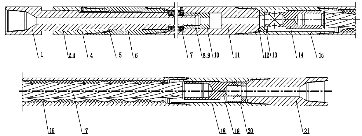
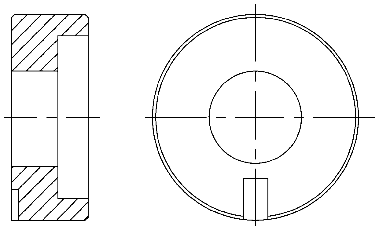
[0016] like Figure 1-Figure 6 As shown, a tool for reducing the friction between the drilling tool and the well wall, its structure mainly includes: a slide rod 1, a sealing ring 2, a retaining ring 3, a first upper casing 4, a limiting semi-circular ring 5, Second upper case 6, disc spring 7, sealing ring 8, retaining ring 9, piston 10, third upper case 11, ordinary flat key 12, upper fixed valve 13, upper moving valve 14, fourth upper case 15 , stator 16, rotor 17, lower casing 18, lower moving valve 19, lower fixed valve 20, lower interface 21; its technical features are: first upper casing 4, second upper casing 6, third upper casing 11 , the fourth upper casing 15, the stator 16, the lower casing 18, and the lower interface 21 are threaded sequentially from top to bottom; there is a round hole-shaped flow channel inside the slide rod 1, and the lower end of the slide rod 1 is installed on the first upper casing 4. In the inner hole of the second upper case 6, there is c...


PUM


Abstract

The invention relates to a tool for reducing friction between a drilling tool and a well wall, improving well drilling efficiency and shortening a well drilling cycle and a method thereof. According to the technical scheme, the tool for reducing the friction between the drilling tool and the well wall mainly comprises a sliding rod, a sealing ring, a check ring, a first upper shell, a limiting semi-circular ring, a second upper shell, a disc spring, a sealing ring, a check ring, a piston, a third upper shell, a common flat key, an upper fixed valve, an upper moving valve, a fourth upper shell,a stator, a rotor, a lower shell, a lower moving valve, a lower fixed valve and a lower interface, wherein the first upper shell, the second upper shell, the third upper shell, the fourth upper shell, the stator, the lower shell and the lower interface are in threaded connection in sequence, under the driving of the rotor, an inclined hole runner of the lower moving valve is periodically opened and closed, the energy of fluid is converted into a series of pulse pressures, and static friction between the drilling tool and the well wall is broken, so that the purpose of reducing the friction and improving the drilling capacity of a horizontal section is achieved.

Description

technical field [0001] The invention relates to a tool for reducing the forward friction resistance of drill strings in directional wells, extended displacement wells and horizontal wells, and improving the extension ability of the horizontal section of directional wells, extended displacement wells and horizontal wells. Background technique [0002] With the continuous increase of human demand for oil resources and the continuous reduction of oil and gas resources around the world, in order to meet human needs for oil resources, complex oil and gas reservoirs such as low permeability, low pressure and low porosity have been developed. Directional wells, extended-reach wells and horizontal wells are also more and more widely used; at present, with the continuous progress of oil and gas reservoir exploration and development technology, the proportion of directional wells, horizontal wells and extended-reach wells in oil and gas reservoir exploration and development In the dri...

Claims


Application Information

Patent Timeline
Patent Type & Authority Applications(China)
IPC IPC(8): E21B7/24E21B17/00
CPCE21B7/24E21B17/00
Inventor 石昌帅李金平祝效华
Owner SOUTHWEST PETROLEUM UNIV
Learn More