Liquid foaming agent injection method

A foaming agent, liquid technology, applied in the field of natural gas exploitation, can solve the problems of large capillary usage, limited usage, and high cost, and achieve the effects of improving utilization, reducing usage, and reducing costs

Active Publication Date: 2012-10-24
CHINA UNIV OF PETROLEUM (EAST CHINA)
View PDF6 Cites 12 Cited by
  • Summary
  • Abstract
  • Description
  • Claims
  • Application Information

AI Technical Summary

Problems solved by technology

The advantage of this method is: the foaming agent can be well injected into the bottom of the well to better mix with the bottom fluid, improving the utilization rate of the foaming agent and the drainage effect; the disadvantage is that the amount of capillary used is large, resulting in cost too high
[0003] Therefore, in order to solve the above two injection methods, although they have their own advantages, their shortcomings are also relatively obvious, and their use is subject to certain restrictions.

Method used


Image

  • Liquid foaming agent injection method
  • Liquid foaming agent injection method

Examples


Embodiment Construction

[0015] combined with figure 1 and figure 2 , to further describe the present invention:

[0016] A method for injecting a liquid foaming agent provided by the invention is realized by the following method:

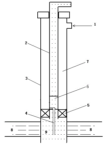
[0017] (1) Install a packer 5 at the shoe of the tubing 2 to isolate the oil casing annulus 7 from the well bottom 9;

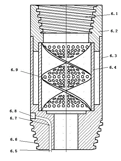
[0018] (2) A shorting 6 is installed on the upper part of the packer 5. There is a foaming agent channel on the side of the shorting to connect the oil jacket annulus with the lower part of the shorting. The lower part of the shorting is provided with a capillary interface, and the capillary 4 is installed on the lower part of the shorting 6 The interface is connected to the liquid accumulation in the middle and lower part of the well bottom 9, and the center of the short-circuit is provided with a twisted porous plate, which is connected with the tubing 2;

[0019] (3) The foaming agent is injected into the oil casing annulus 7 from the foaming a...


PUM


Abstract

The invention relates to a liquid foaming agent injection method, belonging to the field of natural gas exploitation. The method comprises the following steps: (1) mounting a packer at a pipe shoe of an oil pipe to separate the oil sleeve annulus and the well bottom; (2) mounting a short coupling on the upper part of the packer, wherein the side surface of the short coupling is provided with a foaming agent channel which communicates the oil sleeve annulus with the lower part of the short coupling, and the lower part of the short coupling is connected with capillaries and communicated to an accumulated liquid on the middle lower part of the well bottom all along; (3) injecting the foaming agent from a well mouth oil sleeve annulus gate to the oil sleeve annulus, wherein the foaming agent resides and gathers at the oil sleeve annulus on the upper part of the packer, and enters the accumulated liquid through the foaming agent channel of the short coupling and the capillaries on the lower part; and (4) mixing natural gas and the foaming agent solution, wherein the mixture passes through a torsional porous plate at the center of the short coupling, enters the oil pipe on the upper part, and is finally discharged. The invention enhances the utilization ratio of the foaming agent, the mixing degree of the foaming agent with the well bottom accumulated liquid, and the foaming efficiency, reduces the use amount of capillaries, and lowers the cost.

Description

technical field [0001] The invention relates to a foam drainage gas recovery technology in the field of natural gas exploitation, in particular to a method for injecting a liquid foaming agent. Background technique [0002] In natural gas exploitation, after water is released from gas reservoirs, liquid accumulation will gradually form at the bottom of the well, seriously affecting the production capacity of natural gas. Foam drainage gas recovery technology is to add a foaming agent into the wellbore to make the natural gas and bottom-hole fluid to form foam, and use the foam to discharge the wellbore fluid, so that the gas well can resume production and prolong the production period, so as to improve the final recovery of the gas reservoir rate purposes. The foaming agent is generally selected from the existing commercially available foaming agents according to the properties and temperature of the gas well fluid. For specific methods and standards, please refer to the pe...

Claims


Application Information

Patent Timeline
Patent Type & Authority Applications(China)
IPC IPC(8): E21B43/22
Inventor 李宾飞李兆敏李松岩刘红军张新军刘昊
Owner CHINA UNIV OF PETROLEUM (EAST CHINA)
Why Eureka
Try Eureka