Liquid passing type electric-control layered polymer filling device

A technology of injector and polymer, which is applied in the direction of mining fluid, measurement, wellbore/well parts, etc., can solve the problems of low work efficiency, large viscosity loss, and inability to adjust continuously, so as to achieve good sealing effect and balance internal and external pressure Poor, precisely measured effects

Inactive Publication Date: 2012-10-24
HARBIN INST OF TECH
View PDF5 Cites 14 Cited by
  • Summary
  • Abstract
  • Description
  • Claims
  • Application Information

AI Technical Summary

Problems solved by technology

[0003] The purpose of the present invention is to provide a liquid-passing electronically controlled layered polymer dispenser to solve the problems of low working efficiency, large viscosity loss and non-continuous adjustment in the current downhole polymer injection equipment.

Method used


Image

  • Liquid passing type electric-control layered polymer filling device
  • Liquid passing type electric-control layered polymer filling device
  • Liquid passing type electric-control layered polymer filling device

Examples


specific Embodiment approach 1

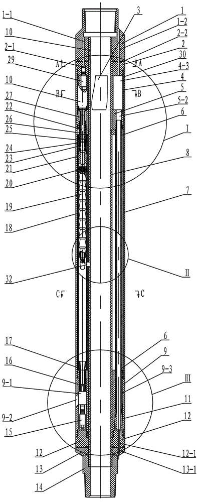
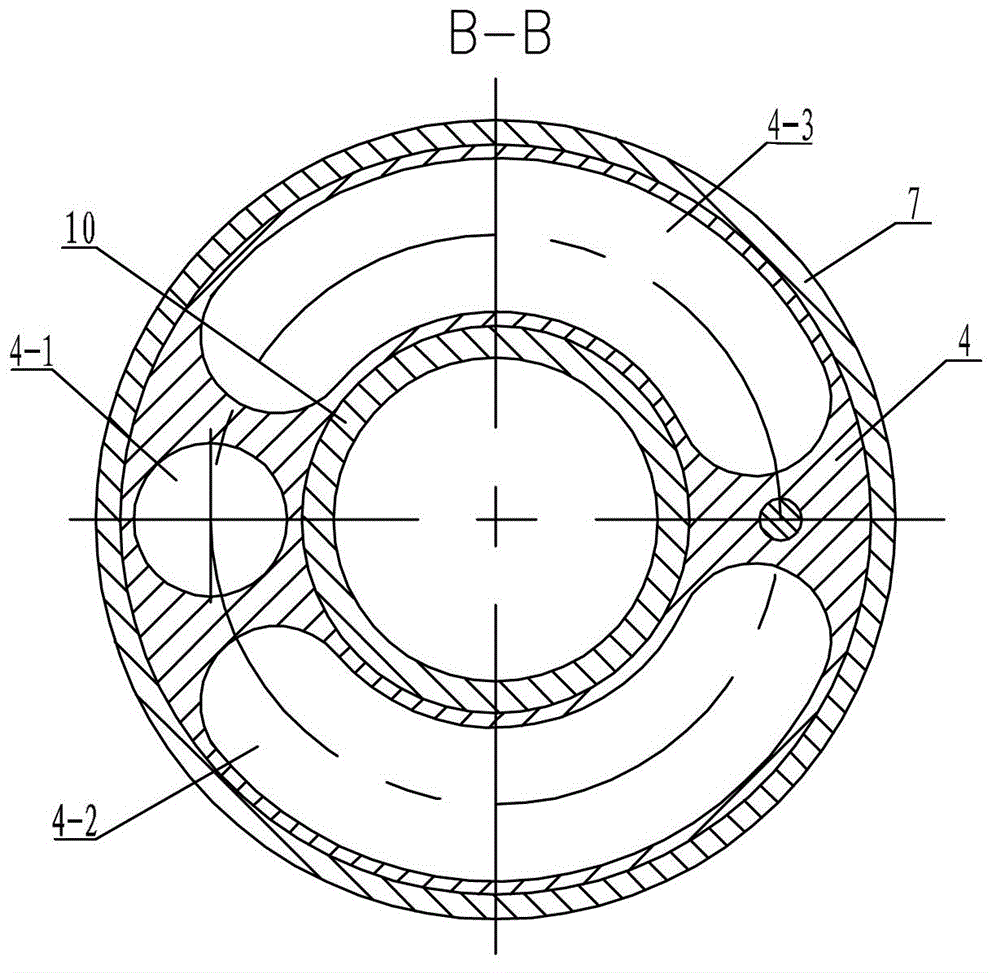
[0009] Specific implementation mode one: combine Figure 1 to Figure 7 This embodiment is described. The liquid-type electronically controlled layered polymer dispenser of this embodiment includes an upper joint 1, a cable sealing body 2, a circuit board 3, a motor casing 4, an output shaft connector 5, and a cable casing 6 , the lower outer protective shell sleeve 7, the lower central tube 8, the bottom cable joint body 9, the upper central tube 10, the lower cable sealing body 11, the bottom cable housing 12, the lower compression sealing body 13, the locking nut joint 14, Lower pressure sensor 15, bottom spool sealing body 16, water blocking body 17, spool body 18, spool 19, screw nut 20, rotating sealing body 21, screw rod 22, bearing assembly 23, bearing sleeve 24, lock nut 25. Screw end connecting body 26, coupling 27, motor reducer 28, upper outer protective shell 30 and anti-rotation body 31, the upper central tube 10 and the lower central tube 8 are set up and down, a...

specific Embodiment approach 2

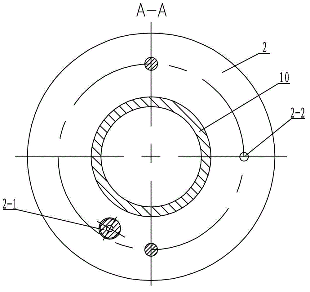
[0010] Specific implementation mode two: combination figure 1 , Figure 5and Figure 7 Describe this embodiment, the difference between this embodiment and specific embodiment 1 or 2 is that it also adds upper pressure sensor 29, is provided with solution through hole 1-1 on the side wall of upper connector 1, and the solution through hole 1-1 The upper end communicates with the central hole of the upper joint 1, and the cable sealing body 2 is provided with an upper pressure sensor installation hole 2-1 communicated with the solution through hole 1-1, and the lower end of the upper pressure sensor installation hole 2-1 is a threaded hole, the pressure The lower end of the sensor mounting hole 2-1 communicates with the circuit board hole 4-2, the upper pressure sensor 29 is arranged in the circuit board hole 4-2, and the upper end of the upper pressure sensor 29 is threaded with the lower end of the upper pressure sensor mounting hole 2-1 connect. The polymer solution in th...


PUM


Abstract

The invention provides a liquid passing type electric-control layered polymer filling device, which relates to underground polymer driving equipment and solves the problems of the existing underground polymer filling equipment that the working efficiency is low, the viscosity loss is great and the continuous adjustment cannot be realized. A motor reducer drives a screw rod to rotate; a screw moves up and down along the screw rod; a valve core continuously moves in a pipe body of the valve core up and down along with the screw; a lower pressure sensor is mounted in a vertical hole, and an upper pressure sensor is arranged in a circuit board hole; radial through holes are formed on the side walls of a lower central pipe and the pipe body of the valve core; a solution outlet is arranged on the side wall of a cable connector body; and a cable penetrates from a cable through hole of an upper connector, and then stretches out from a through hole of a lower pressing sealing body after passing through a cable through hole of a cable sealing body, a cable hole, a cable through hole of an output shaft connecting body, an inner cavity of a cable shell and a through hole of a bottom cable shell. The liquid passing type electric-control layered polymer filling device disclosed by the invention is used for filling polymers to extract oil.

Description

technical field [0001] The invention relates to a downhole polymer driving device. Background technique [0002] As the world's demand for oil continues to increase, as oil is a limited non-renewable energy source, the chances of rediscovering larger oil storage oil fields are reduced, the developed oil fields are aging, and most of the unexploited oil fields are heavy oil fields, which forces people to use Attention is directed to enhanced oil recovery technologies for mature oilfields. As an important method of chemical driving in tertiary oil recovery, polymer driving is the main means of crude oil recovery at present. However, due to the high viscosity of the polymer and the complex downhole environment, the current artificial fishing technology and polymer injection equipment cannot achieve the functions of flow monitoring, accurate flow injection, and layered polymer injection. Therefore, it is necessary to vigorously develop a new type of high-efficiency polymer inje...

Claims


Application Information

Patent Timeline
IPC IPC(8): E21B43/22E21B47/06
Inventor 张广玉李隆球周德开黄有泉赵望王武义
Owner HARBIN INST OF TECH
Why Eureka
Try Eureka