Vacuum-tube type solar air collector

An air heat collector and vacuum tube technology, applied in solar heat collectors, solar heat collectors using working fluid, solar thermal energy, etc., can solve the problems of large heat loss and low heat collection efficiency, and achieve small convective heat loss , Low heat reflectivity, easy to clean

Inactive Publication Date: 2012-10-24
HUHHOT BRANCH OF CHINESE ACAD OF AGRI MECHANIZATION SCI +1
View PDF0 Cites 5 Cited by
  • Summary
  • Abstract
  • Description
  • Claims
  • Application Information

AI Technical Summary

Problems solved by technology

The air collector with this structure is simple in structure and low in cost, but the heat collection efficiency of this air collector is low and the heat loss is large

Method used


Image

  • Vacuum-tube type solar air collector
  • Vacuum-tube type solar air collector

Examples


Embodiment Construction

[0015] The present invention is described further according to accompanying drawing:

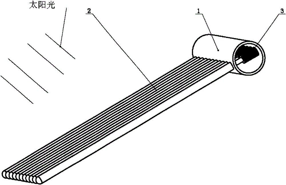
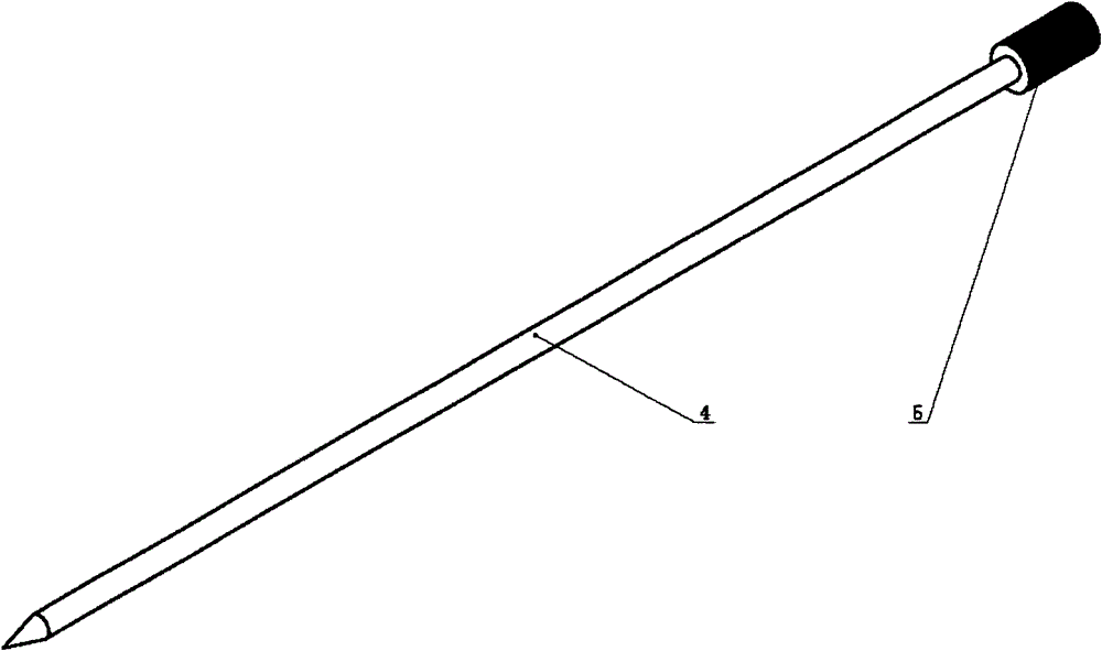
[0016] A kind of vacuum tube solar air heat collector, its overall structure is as follows figure 1 As shown, there are mainly a box body 1, a glass vacuum tube 2, and a heat collecting core 3. The structure diagram of the heat collecting core is as follows: figure 2 Shown, heating pipe 4, fin 5 are arranged. like figure 1 As shown, the sunlight shines on the glass vacuum tube 2, and the heating tube 4 is heated by the glass vacuum tube 2. The heating tube 4 is connected to the fin 5, and the fin 5 heats the air in the box body 1. The two ends of the box body 1 are open, and the air flows from the side of the box body 1. One end flows through the fins 5, and the other end flows out to take away the heat on the fins 5.


PUM


Abstract

The invention relates to a vacuum-tube type solar air collector. The vacuum-tube type solar air collector mainly comprises an all-glass vacuum tube, a heat collecting core and a case body, wherein the heat collecting core is installed inside the vacuum tube, a vane exposed out of the heat collecting core extends into the case body, and two ends of the case body are provided with openings for ventilation. In the working process, the sunlight penetrates through the vacuum tube, the heat collecting core is heated through the vacuum tube, the heat is transmitted to the radiating fin through the heat collecting core, the heat on the fin surface is taken away through the ventilation in the case body, and the air is heated. The solar air collector is simple in design and manufacturing process, mature and reliable in technology, low in cost and capable of being used in a large scale and in an integration mode. The contiguous integration of collectors can be achieved in accordance with requirements.

Description

technical field [0001] The invention belongs to the field of development and utilization of renewable energy, in particular to a vacuum tube solar air heat collector. Background technique [0002] In the existing technology, the vast majority of solar air collectors are plate heat collectors, the heat collecting core adopts a plate structure, the heat collecting plate is coated with selective heat absorbing paint, and the heat collecting plate has a transparent cover plate. The wall is insulated, and the sunlight passes through the transparent cover plate and shines on the heat collecting plate, heating the heat collecting plate, releasing heat through the heat collecting plate, and heating the air in the heat collector. The air heat collector with this structure is simple in structure and low in cost, but the heat collection efficiency of this air heat collector is low and the heat loss is large. Contents of the invention [0003] The purpose of the present invention is ...

Claims


Application Information

Patent Timeline
Patent Type & Authority Applications(China)
IPC IPC(8): F24J2/05F24J2/46F24S10/40
CPCY02E10/44
Inventor 贺刚刘贵林
Owner HUHHOT BRANCH OF CHINESE ACAD OF AGRI MECHANIZATION SCI
Why Eureka
Try Eureka