Photoelectric type derrick deflection detection device and detection method thereof

A technology of pole deflection and detection device, which is applied to measurement devices, optical devices, instruments, etc., can solve problems such as the inability to meet application requirements, and achieve the effects of simple structure, low cost and large measuring range.

Inactive Publication Date: 2014-11-05
HEFEI UNIV OF TECH
View PDF7 Cites 4 Cited by
  • Summary
  • Abstract
  • Description
  • Claims
  • Application Information

AI Technical Summary

Problems solved by technology

Because the model and prototype of the pole are very different in materials, processing, etc., the results of the model test are often quite different from the actual situation, which cannot meet the needs of the application.

Method used


Image

  • Photoelectric type derrick deflection detection device and detection method thereof
  • Photoelectric type derrick deflection detection device and detection method thereof
  • Photoelectric type derrick deflection detection device and detection method thereof

Examples


Embodiment Construction

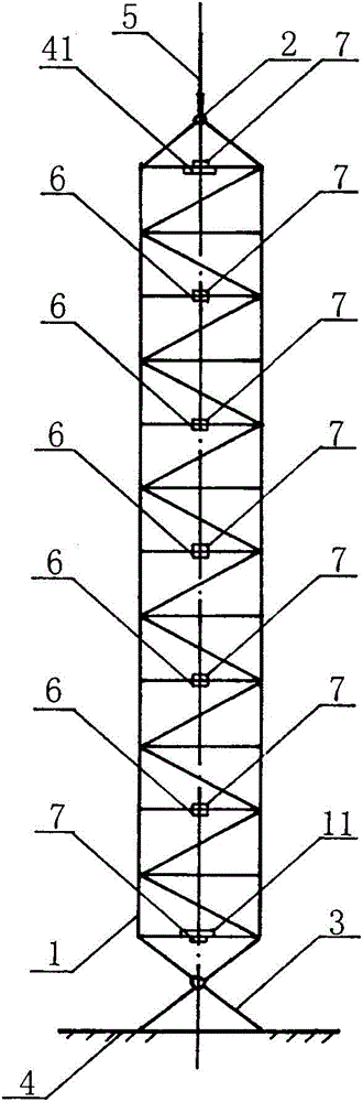
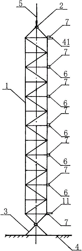
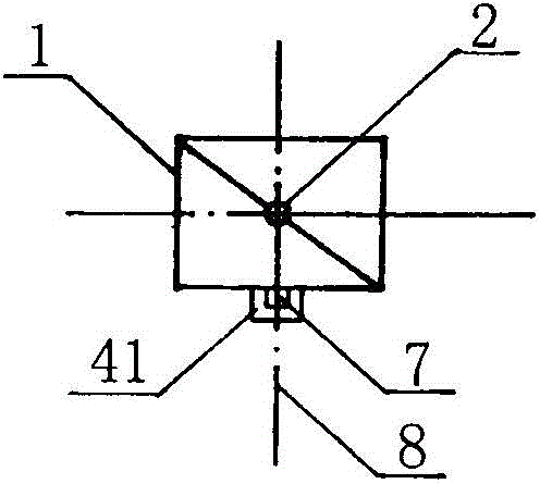
[0022] A photoelectric pole deflection detection device, such as figure 1 , 2As shown in and 3, it includes a pole 1, a support 3, a foundation 4, a laser transmitter 11, a laser receiver 41, a deflection detector, several light interceptors 6, several inclination sensors 7, a bearing hinge 2 and a load 5, The lower end of the pole 1 is connected to the support 3, the support 3 is fixed on the foundation 4, and the laser receiver 41 is placed on the upper end of the pole 1 on the outer side of the small direction of the cross-sectional moment of inertia. And an inclination sensor 7, described laser emitter 11 and an inclination sensor 7 are arranged at the lower end, and described light cutoff device 6 and inclination sensor 7 are arranged equidistantly in the middle, described laser emitter 11, laser receiver 41. Both the light chopper 6 and the inclination sensor 7 are located on the centerline 8 of the outer surface in the direction of the small moment of inertia of the se...


PUM


Abstract

The invention discloses a photoelectric type derrick deflection detection device and a detection method thereof. The device comprises a laser emitter, a laser receiver, optical choppers, inclination sensors and a deflection detector, wherein the laser receiver and an inclination sensor are arranged at the upper end of a derrick, the laser emitter and an inclination sensor are arranged at the lower end of the derrick, and optical choppers and inclination sensors are arranged on all detection points of the middle of the derrick. When end portions of the derrick are subjected to a load action, the whole deflection of the derrick can be detected. According to the photoelectric type derrick deflection detection device and the detection method thereof, the device can detect the whole deflection value and a destabilization state after force is exerted on the derrick, bases are provided for the force analysis of the derrick, the optimization design of the derrick and the quality detection of the derrick, the precision is high, the range is wide, the accuracy is good, the structure is simple, the operation is simple, the producing cost is low and the data can be displayed in real time.

Description

technical field [0001] The invention relates to a test device for detecting the deflection of a pole under force, in particular to a photoelectric pole deflection detection device and a detection method thereof. Background technique [0002] At present, the method of combining theoretical calculation and experimental stress analysis is commonly used to optimize the design of the pole-holding structure. In this experimental stress analysis method, a resistance strain gauge is generally pasted on the member holding the pole, and the strain of the member after being stressed is measured, and the strength value of the member is obtained through conversion. For the overall deflection and stiffness of the pole after being stressed, it can only be obtained by doing model tests. Because the model and prototype of the pole are very different in materials and processing methods, the results of the model test are often quite different from the actual situation, which cannot me...

Claims


Application Information

Patent Timeline
Patent Type & Authority Patents(China)
IPC IPC(8): G01B11/16
Inventor 周焕林柳兆涛胡宗军
Owner HEFEI UNIV OF TECH
Why Eureka
Try Eureka