
Method for reducing working blind zone of ultrasonic transducer on the basis of excitation energy control

A technology of working blind area and exciting energy, applied in the re-radiation of sound waves, instruments, measuring devices, etc., can solve problems such as inconvenience in measurement, and achieve the effect of broadening the range, reducing the working blind area, and reducing the installation distance requirements.

Inactive Publication Date: 2012-10-24
ZHEJIANG UNIV
View PDF5 Cites 22 Cited by
  • Summary
  • Abstract
  • Description
  • Claims
  • Application Information

AI Technical Summary

Problems solved by technology

This method will cause great inconvenience for the flow or object position measurement of some closed pipes or containers

Method used


Image

  • Method for reducing working blind zone of ultrasonic transducer on the basis of excitation energy control
  • Method for reducing working blind zone of ultrasonic transducer on the basis of excitation energy control
  • Method for reducing working blind zone of ultrasonic transducer on the basis of excitation energy control

Examples


Embodiment Construction

[0021] The specific implementation manner of the present invention will be described in detail below in conjunction with the accompanying drawings and examples.

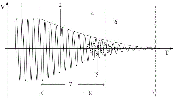
[0022] Such as figure 1 Shown is a schematic diagram of the working blind area of ​​the ultrasonic transducer. The frequency of the ultrasonic excitation signal 1 is the same as the resonance frequency of the ultrasonic transducer. Therefore, after the ultrasonic excitation signal 1 enters the ultrasonic transducer, it can cause the ultrasonic transducer to resonate and excite the ultrasonic excitation signal. However, when the ultrasonic excitation signal 1 disappears, due to the residual energy during the excitation, the energy conversion element inside the ultrasonic transducer will continue to vibrate due to mechanical inertia and electrical inertia (free decay oscillation), resulting in aftershock signal 2. From the amplitude envelope 3 of the aftershock signal, it can be seen that the vibration of the aftersh...


PUM


Abstract

The invention discloses a method for reducing a working blind zone of an ultrasonic transducer on the basis of excitation energy control. After an ultrasonic flow or object position measuring instrument is started or reset, the instrument sets an ultrasonic exciting pulse to generate an ultrasonic exciting signal, wherein the ultrasonic exciting pulse has excitation energy, and the number of the ultrasonic exciting pulse is one less than the number of the ultrasonic exciting pulse required for generating an ultrasonic exciting signal with a plateau characteristic; an ultrasonic echo signal corresponding to the ultrasonic exciting signal is utilized to measure the flow or object position; when the flow or object position is not changed, measurement is respectively carried for more than two times; a measurement result is compared with a preset value; ultrasonic excitation energy is regulated in a self-adaption mode by a result obtained by comparing the measurement result with the preset value so as to control the residual energy of the ultrasonic transducer; the working blind zone of the ultrasonic transducer is reduced; and the measurable acoustic-path range of the ultrasonic is widened.

Description

technical field [0001] The invention relates to a method for reducing the working blind area of ​​an ultrasonic transducer, in particular to a method for reducing the working blind area of ​​the ultrasonic transducer based on excitation energy control. Background technique [0002] Ultrasonic measurement technology has been widely used and highly recognized in modern industry because of its high measurement accuracy, wide range, and good reliability. The key to ultrasonic measurement technology lies in the detection of ultrasonic echo signals. The so-called ultrasonic echo signals are for ultrasonic excitation signals, which means that after the same ultrasonic transducer transmits ultrasonic excitation signals, the ultrasonic excitation signals pass through different media interfaces. (such as water and air, water and metal, etc.) reflected ultrasonic signals or ultrasonic signals that are sent back after receiving the ultrasonic excitation signal through another transducer...

Claims


Application Information

Patent Timeline
Patent Type & Authority Applications(China)
IPC IPC(8): G01F1/66G01S15/06
Inventor 傅新毛凯胡亮
Owner ZHEJIANG UNIV
Learn More