Novel flexural member sustained loading test device based on secondary level effect
A loading test device and flexural member technology, which is applied in the direction of applying a stable bending force to test the strength of materials, can solve the problems of the performance degradation of flexural members and the incompatibility of the joint action, and achieve stable loading performance, stable load, and load level. adjustable effects
- Summary
- Abstract
- Description
- Claims
- Application Information
AI Technical Summary
Problems solved by technology
Method used
Image
Examples
Embodiment 1
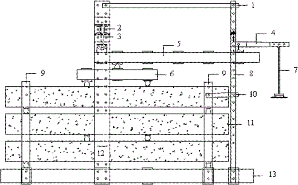
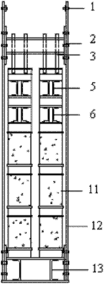
[0024] Such as Figure 1~2 , 5, a new type of continuous loading test device for bending members based on secondary leverage. Disk 7, steel plate b8, dial indicator support 9, diagonal brace b10, bending test piece 11, steel plate a12, reaction beam 13, and static data acquisition system, the static data acquisition system includes pressure sensor 14, data acquisition instrument 15 and PC16.
[0025] The steel plate b8 is in the shape of a U-shaped frame, and the steel plate a12 is in the shape of a U-shaped frame. The steel plate b8 and the steel plate a12 form a bracket. The top of the steel plate b8 and the steel plate a12 are connected by a diagonal brace a1. The end is connected by the embedded beam 2 and the screw rod 3. The upper part of the steel plate b8 is fixed to the lever beam b4 protruding outward. One end of the lever beam b4 hangs the weight suspension pan 7, and the other end is fixed on the steel plate b8. The lever beam a5 is set on the steel plate b8 Betw...
PUM
 Abstract
Description
Claims
Application Information
 - R&D
- Intellectual Property
- Life Sciences
- Materials
- Tech Scout
- Unparalleled Data Quality
- Higher Quality Content
- 60% Fewer Hallucinations
Browse by: Latest US Patents, China's latest patents, Technical Efficacy Thesaurus, Application Domain, Technology Topic, Popular Technical Reports.
© 2025 PatSnap. All rights reserved.Legal|Privacy policy|Modern Slavery Act Transparency Statement|Sitemap|About US| Contact US: help@patsnap.com


