
Nylon polarized lens and forming mold thereof

一种偏光镜片、成型模具的技术,应用在其他家里用具、光学、光学部件等方向,能够解决镜片厚等问题,达到减少加工程序、利用率提高、避免冲胶现象的效果

Inactive Publication Date: 2012-10-24
XIAMEN HONGTAI ELECTRONICS OPTICAL C O
View PDF10 Cites 5 Cited by
  • Summary
  • Abstract
  • Description
  • Claims
  • Application Information

AI Technical Summary

Problems solved by technology

However, in this way, the thickness of the obtained lens is usually about 3 mm. Therefore, this patent is not suitable for making thin polarized lenses. Of course, thicker lenses require more materials, and this patent is not suitable for polarized lenses with expensive materials. , such as nylon polarized lenses

Method used


Image

  • Nylon polarized lens and forming mold thereof
  • Nylon polarized lens and forming mold thereof
  • Nylon polarized lens and forming mold thereof

Examples


Embodiment 1

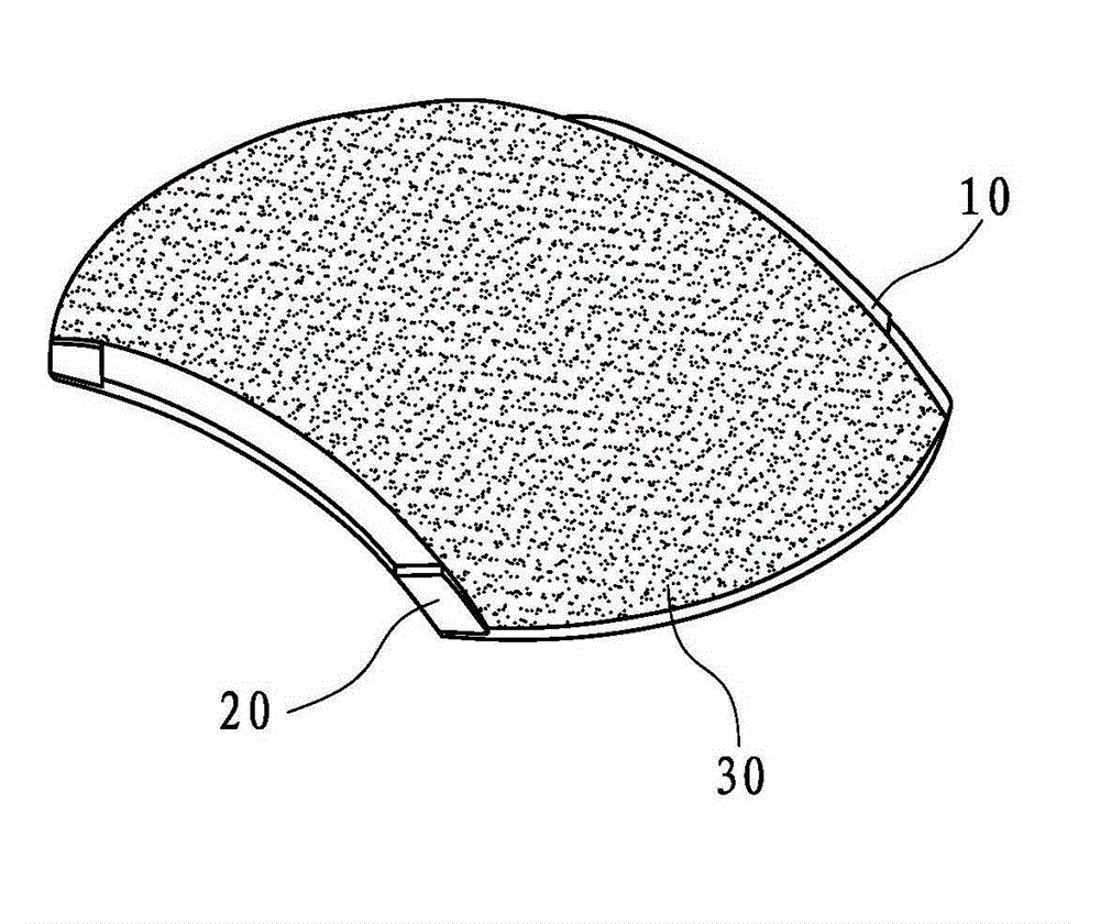
[0042] Such as Figure 8 Shown is the first embodiment of a nylon polarizing lens disclosed in the present invention, which is composed of a nylon material layer 100 and a polarizing film 30 . A positioning part for positioning the polarizing film 30 is respectively formed at four corners of the nylon material layer 100. There are many specific forms of the positioning part. Figure 8 The positioning portion shown is the concave portion 20 , and a polarizing film 30 is combined on the outer surface of the area surrounded by the four concave portions 20 . The key of the present invention is that buffer grooves 1 are provided on the end faces of the two opposite sides of the nylon material layer 100 .

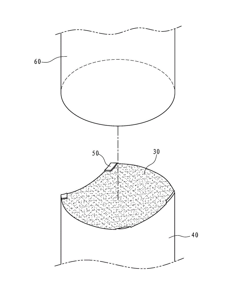
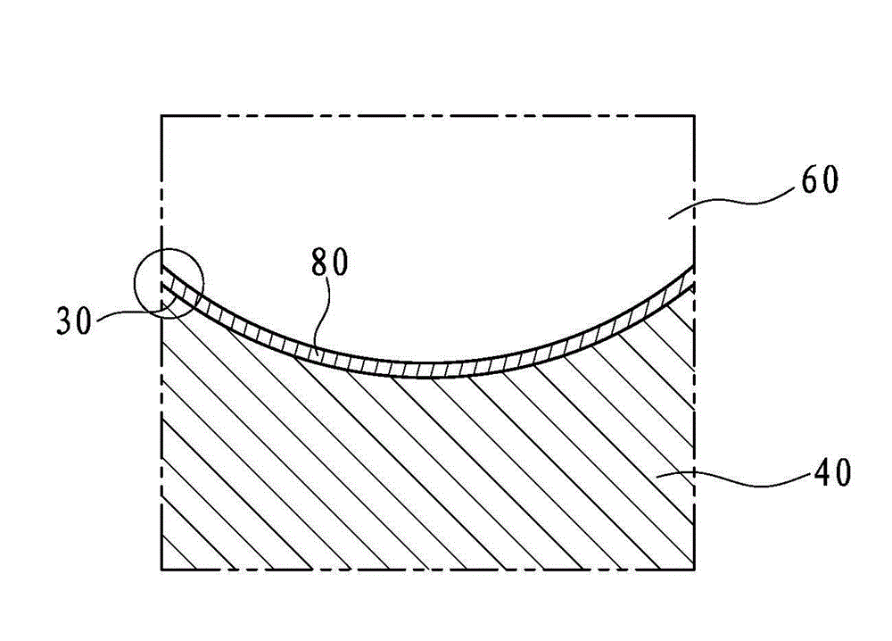
[0043] Cooperate Figure 9 and Figure 10 As shown, the forming mold for preparing the above-mentioned nylon polarized lens is composed of an upper mold 60 and a lower mold 40 . The top end surface of the lower mold 40 is an arc concave surface, and a buffer rib 2 is formed o...

Embodiment 2

[0046] Another example Figure 11 Shown is the second embodiment of a nylon polarizing lens disclosed in the present invention, which is composed of a nylon material layer 100 and a polarizing film 30 . Form a positioning portion for positioning the polarizing film 30 at four corners of the nylon material layer 100 respectively, and this embodiment positioning portion forms aperture 3 at four corners of the nylon material layer 100, and aperture 3 is for the die described later The positioning pin penetrates through to position the polarizing film 200 . The key of the present invention is that buffer grooves 1 are provided on the end faces of the two opposite sides of the nylon material layer 100 .

[0047] In this embodiment, the two opposite sides of the nylon material layer 100 extend to both sides to form a positioning plane 4, and four corners of the outer surfaces of the two positioning planes 4 are respectively formed with protruding top feet 5, which can be supported ...


PUM


Abstract

The utility model discloses a nylon polarized lens which comprises a nylon material layer and a polarized film, wherein a positioning part for positioning the polarized film is formed at each of the four corners of the nylon material layer, and buffering grooves are arranged at the end surface of two opposite edges of the nylon material layer. A forming mold for preparing the nylon polarized lens comprises an upper mold and a lower mold. The top end face of the lower mold is an arch concave face, and a buffering rib for molding a lens buffering slot and a positioning part for positioning the polarized film are formed on the top end face of the lower mold; and the bottom end face of the upper mold is an arch convex face, and the upper mold approaches the lower mold to form a mold chamber for molding the lens. The nylon polarized lens and the forming mold are suitable for manufacturing a polarized lens which has a thin mode and expensive materials, and improve the yield and the product quality.

Description

technical field [0001] The invention relates to a nylon polarized lens and a molding die for preparing the nylon polarized lens. Background technique [0002] At present, common polarized lenses are mostly made of PC material (polycarbonate), because PC lenses are light (only one-tenth of the same volume of glass, only half the weight of traditional resin lenses), durable (with anti- The physical properties of impact and deformation resistance, under strong impact, the chaps will not break, and there will be no fragments to break - so-called safety lenses), environmental protection (thermosetting materials, which can be recycled into other industrial products and have regeneration properties), but, The biggest disadvantage of PC polarized lenses is that they are not acid-resistant, so they cannot be used in the more popular sheet frames in the market, and PC polarized light injection molding produces internal stress, and stress concentration occurs during the assembly proces...

Claims


Application Information

Patent Timeline
Patent Type & Authority Applications(China)
IPC IPC(8): G02C7/12G02B1/10B29C45/26
CPCB29D11/00644B29D11/0073B29D11/0049G02C7/12B29D11/0048
Inventor 陈宇翔
Owner XIAMEN HONGTAI ELECTRONICS OPTICAL C O
Learn More