Drying device for electrodeless lamp

A technology of baking device and electrodeless lamp, which is applied in the direction of electric tube/lamp exhaust, etc., can solve the problem of different baking effect of lamp tube, and achieve the effect of uniform baking temperature

Inactive Publication Date: 2014-12-24
SHAOXING UNIVERSITY
View PDF3 Cites 0 Cited by
  • Summary
  • Abstract
  • Description
  • Claims
  • Application Information

AI Technical Summary

Problems solved by technology

In the existing baking system, the baking effect of the same batch of lamps is different, especially after a long baking time, the problem is particularly obvious

Method used


Image

  • Drying device for electrodeless lamp
  • Drying device for electrodeless lamp

Examples


Embodiment Construction

[0014] The preferred embodiments of the present invention will be described in further detail in conjunction with the accompanying drawings.

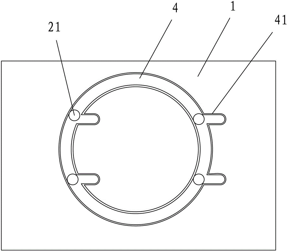
[0015] An electrodeless lamp baking device, comprising a workbench 1, an oven 2, and a feeding track 3.

[0016] The oven 2 is used for drying the cabinet of the electrodeless lamp, and the oven 2 adopts an internal heating method. The structural principle of the oven itself is a conventional technical means in the field, and will not be described here.

[0017] In this embodiment, the two ends of the oven 2 pass through the oven body. The traditional baking method is to arrange a through track in the oven 2, and the electrodeless lamp enters from one end and exits from the other end. In the present invention, the feeding track 3 is a track of a telescopic structure, and is only arranged at one end of the oven 2 . In this way, the electrodeless lamp tube is placed on the feeding track 3, and the electrodeless lamp tube is sent into the...


PUM


Abstract

The invention mainly discloses a drying device for an electrodeless lamp. The drying device comprises a workbench, a drying box, and a feeding rail, wherein two ends of the drying box penetrate through the body of the drying box, the feeding rail is arranged at one end of the drying box, and the bottom of the drying box is connected with the workbench through an annular rail. The drying device has a simple structure, is convenient in heating, and can ensure that the whole drying box can dry a lamp tube stably and uniformly.

Description

technical field [0001] The invention relates to the technical field of equipment involved in the production process of an electrodeless lamp, in particular to a baking device for an electrodeless lamp. Background technique [0002] During the production process of the electrodeless lamp, one of the processes is exhaust. Although the gas molecules that move inside the shell or device are easier to be removed by the vacuum pump during the exhaust, the gas molecules that are adsorbed on the inner wall of the shell and penetrate into the material of the tube The gas is not easy to be extracted, so the shell must be heated and baked to increase the escape energy of the gas, accelerate the escape of gas molecules and be extracted by the vacuum pump in time. The baking system is one of the key components in the production process of the electrodeless lamp. The baking system with a suitable temperature is conducive to the extraction of the adsorbed gas in the tube. In the existing ...

Claims


Application Information

Patent Timeline
Patent Type & Authority Patents(China)
IPC IPC(8): H01J9/385
Inventor 张新华张若煜
Owner SHAOXING UNIVERSITY
Why Eureka
Try Eureka