Switch reluctance electromotor with function of power-off self locking

A technology of switched reluctance and motors, which is applied in the direction of magnetic circuit rotating parts, electrical components, electromechanical devices, etc., and can solve problems such as potential safety hazards, waste of electric energy, and consumption of friction materials

Active Publication Date: 2012-10-24
戴珊珊
View PDF4 Cites 7 Cited by
  • Summary
  • Abstract
  • Description
  • Claims
  • Application Information

AI Technical Summary

Problems solved by technology

[0002] The rotor salient poles of existing doubly salient switched reluctance motors are usually made of iron core materials. When the stator excitation coil has no excitation current, there is no force between the rotor salient poles and the stator salient poles. At this time, if To brake, you can only rely on the force of an external device, such as the friction braking force generated by the friction plate of the brake device acting on the surface of the moving object. This braking method not only consumes friction materials, but also wastes electric energy.
At the same time, there are security risks

Method used


Image

  • Switch reluctance electromotor with function of power-off self locking
  • Switch reluctance electromotor with function of power-off self locking
  • Switch reluctance electromotor with function of power-off self locking

Examples


Embodiment 1

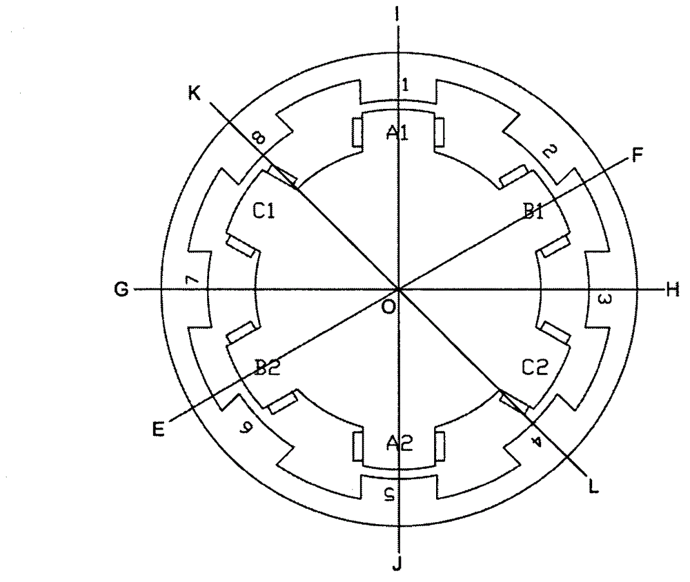
[0063] This embodiment is an outer rotor motor, and its specific structure is as attached Figure 4 attached Figure 5 And attached Figure 6 As shown, the number of rotor "permanent magnet salient pole pairs" in this embodiment is twice the number of stator "excitation salient pole pairs", that is, M=2N, where M is twelve, N is six, and k is 2. In this implementation An example is to solve the motor starting by biasing the two sets of rotor "permanent magnet salient pole pairs" structure.

[0064] Figure 4 It is a structural cross-sectional view of Embodiment 1, (for the convenience of explanation, the equilibrium state generated by the α angle is ignored, and the figure is the actual state for analysis) the stator is composed of a stator base 206 and six "excitation salient pole pairs", and six "excitation pole pairs" The “salient pole pairs” take the rotation axis 208 as the axis of symmetry, and are arranged radially symmetrically on the periphery of the stator seat 20...

Embodiment 2

[0070] The structure of this embodiment is as attached Figure 7-9 shown. The structure of this embodiment is basically the same as that of Embodiment 1, the only difference lies in the winding method and setting position of the excitation coils of the stator "excitation salient pole pairs". In this embodiment, the excitation coils are divided into two groups and wound in series on the salient poles of the iron core, so that the axial length of the motor can be shortened to meet special needs.

[0071] The asymmetric arrangement of the "permanent magnet salient pole pairs" of the rotor in this embodiment, the self-locking mechanism when the motor is powered off, the motor start-up, the operation process, and the automatic air cooling of the motor are the same as those in the first embodiment, and will not be repeated here.

Embodiment 3

[0073] This embodiment is an external rotor motor, the number M of rotor "salient pole pairs" is twice the number N of stator "salient pole pairs", that is, M is 10, N is 5, and k is 2.

[0074] In this embodiment, a structural form of biasing a stator excitation salient pole pair can be adopted to solve the problem of starting the motor. Figure 10 The structural section of this kind of bias mode motor. In the figure, the relative position of the stator and the rotor is an initial state when the motor is de-energized, that is, the self-locking state, and the four excitation salient pole pairs A, C, D, E are respectively facing the permanent magnet salient pole pair I on the rotor. . Another initial state in the case of power failure of the motor in this embodiment, that is, the self-locking state, is that the four excitation salient pole pairs A, C, D, and E are respectively facing the permanent magnet salient pole pairs II, VI, VIII, and X on the rotor. , and there is an o...


PUM


Abstract

The invention relates to a switch reluctance electromotor with the function of power-off self locking. An electromotor stator comprises N excitation salient pole pairs, a rotor comprises M permanent magnet salient pole pairs, N is a natural number which is more than or equal to 2, M is an even number which is more than or equal to 2, M=kN, k is the even number when N is the odd number, k is the natural number when N is the even number, and a closed-magnetic return path is formed by the excitation salient pole pairs and the permanent magnet salient pole pairs under the condition of power off, so that an electromotor can be self-locked. In order to lead the electromotor to be normally turned on, the switch reluctance electromotor adopts the radial asymmetric structure design between some excitation salient pole pairs on the stator or some permanent magnet salient pole pairs on the rotor, so that the electromotor which is self-locked under k statues always has one salient pole of the excitation salient pole pairs on the stator to be shifted relatively to the salient poles of the permanent magnet salient pole pairs on the rotor in a misplacing way, therefore, the electromotor can be guaranteed to be turned on by an confirmed rotation direction. The switch reluctance electromotor is extremely high in self-locking capability under the status of power off, and is simple and reliable in excitation control method.

Description

technical field [0001] The invention relates to the technical field of switched reluctance motors, in particular to a switched reluctance motor with a power-off self-locking function. Background technique [0002] The rotor salient poles of existing double salient pole switched reluctance motors are usually made of iron core materials. When the stator excitation coil has no excitation current, there is no force between the rotor salient poles and the stator salient poles. At this time, if To brake, you can only rely on the force of an external device, such as the friction braking force generated by the friction plate of the brake device acting on the surface of the moving object. This braking method consumes both friction materials and electric energy. At the same time, there are potential safety hazards. [0003] At present, in the practical application of motors, there is a type of motor that needs to be frequently started and braked, such as elevator traction motors, aut...

Claims


Application Information

Patent Timeline
Patent Type & Authority Applications(China)
IPC IPC(8): H02K29/00H02K1/14H02K1/24
Inventor 戴珊珊司雷明朱石柱应展烽
Owner 戴珊珊
Why Eureka
Try Eureka