Machine for cutting web rolls

A technology for cutting equipment and coils, applied in metal processing and other directions, can solve problems such as machine volume increase

Inactive Publication Date: 2012-10-24
FABIO PERINI SPA
View PDF16 Cites 10 Cited by
  • Summary
  • Abstract
  • Description
  • Claims
  • Application Information

AI Technical Summary

Problems solved by technology

The need to use such equipment is necessarily accompanied by a further increase in machine volume and additional process line costs

Method used


Image

  • Machine for cutting web rolls
  • Machine for cutting web rolls
  • Machine for cutting web rolls

Examples


Embodiment Construction

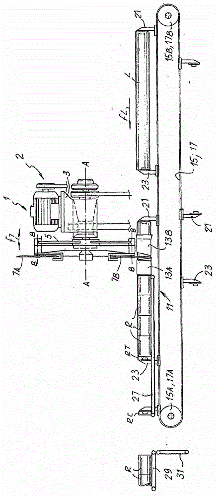
[0030] figure 1 The essential parts of the cutting device are shown schematically. The device has a cutting head 1 with a structure 3 on which a rotating plate 5 is mounted, where A-A designates the axis of rotation of this rotating plate. The rotating plate may support one or more disc-shaped cutting blades. In this example there are two cutting blades 7A and 7B, the line B-B representing the axis of rotation of the cutting blades. The disc-shaped blades 7A, 7B work alternately, in the sense that when the rotating plate 5 rotates about the axis A-A, the disc-shaped blades 7A, 7B sequentially, in the manner described hereinafter, extract from the logs fed through the apparatus. Cut the rolls one by one. It is important to understand that the device can also have a different number of disc-shaped cutting blades, for example only one blade, or three blades, or even more blades on the same rotating plate 5 . In some embodiments, the blades may be paired and coaxial, for examp...


PUM


Abstract

The cutting machine comprises: at least one log feed channel; a cutting station along said feed channel, with at least one cutting blade for dividing each log into individual rolls plus front and rear trims; a log feed device along said feed channel, comprising at least one rear member for pushing the logs to be cut, movable along the feed channel to push each log through said cutting station. The feed device also comprises at least one front member for engaging with the log to be cut, arranged and controlled so as to engage frontally with each log, or series of rolls obtained after the log has been cut, for at least a part of its travel along said feed channel.

Description

technical field [0001] The present invention relates to an apparatus for paper processing, and more particularly to a cutting apparatus for dividing a log of paper or other wound coil material into individual rolls having a smaller axial dimension than the original log . [0002] The invention also relates to a method for processing, especially for cutting, a log of wound web material, typically paper, but not only paper, especially tissue paper, for the production of toilet paper rolls, kitchen paper rolls, etc. Background technique [0003] In the field of paper converting, especially in the production of thin paper products such as toilet paper, kitchen paper, etc., it is common to produce paper rolls with large axial and radial Made directly by feeding a sheet of cellulose fibers from a forming machine. These rolls are subsequently uncoiled and rewound into logs whose diameter dimension corresponds to that of the final product but whose axial dimension corresponds to ...

Claims


Application Information

Patent Timeline
Patent Type & Authority Applications(China)
IPC IPC(8): B26D3/16B26D7/06B26D7/18
CPCB26D5/00B26D3/16B26D7/18B26D2210/02B26D7/01B26D2210/11B26D7/0608B26D7/1836Y10T83/04Y10T83/0448Y10T83/207Y10T83/2092Y10T83/647Y10T83/654Y10T83/6657
Inventor R·马达莱尼M·杰利G·基奥凯蒂
Owner FABIO PERINI SPA
Why Eureka
Try Eureka