Dust humidifying and stirring device
A stirring device and dust technology, which is applied to mixers with rotating stirring devices, mixers, liquid separation agents, etc., can solve the problems of dust accumulation, poor transmission, easy agglomeration, etc., to prolong service life and enhance Wear resistance, the effect of preventing secondary pollution
- Summary
- Abstract
- Description
- Claims
- Application Information
AI Technical Summary
Problems solved by technology
Method used
Image
Examples
Embodiment 1
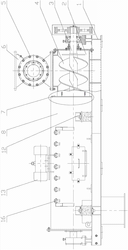
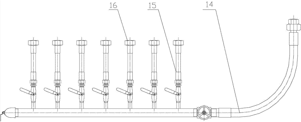
[0021] see Figure 1~4 , the dust humidifying and stirring device of the present invention is composed of a base 1, a feeding cabin 2, a conveying shaft 3, a spiral belt conveying blade 4, a star unloader 5, a blanking cabin 6, a flexible sealing rubber plate 7, a stirring cabin 8, a stirring Shaft 9, stirring rod 10, ceramic sleeve 11, rubber spring seat 12, vibration device 13, low-pressure fluid pipe 14, spray branch pipe 15, nozzle 16 are connected to form.
[0022] A feed cabin 2 is fixedly installed on the base 1, a feed inlet is set on the top wall of the feed cabin 2, a discharge port is set on the side wall, and a conveyor shaft 3 and a spiral belt conveyor blade 4 are arranged in the inner cavity of the feed cabin 2. The spiral belt conveying device, the spiral conveying blade 4 is welded on the conveying shaft 3, the pitch is 150mm, the length of the spiral can be determined according to the length of the conveying shaft, the width of the spiral conveying blade 4 ca...
Embodiment 2
[0025] In this embodiment, the spiral belt conveying device is composed of a conveying shaft 3 and a spiral conveying blade 4, and the spiral conveying blade 4 is welded on the conveying shaft 3 with a pitch of 140mm. In the inner cavity of the stirring chamber 8, a stirring device composed of a stirring shaft 9, a stirring rod 10, and a ceramic sleeve 11 is arranged. The stirring rod 10 is welded on the stirring shaft 9 along the spiral direction of the spiral belt conveying blade 4. The rotation of stirring shaft 9 rotates, and pitch is 140mm, and 3 stirring rods 10 are evenly distributed on a circle of helix, and the included angle α between the center line of each stirring rod 10 and the axis of stirring shaft 9 is 80 °, in A ceramic sleeve 11 with a length of 45 mm is sheathed on the end of each stirring rod 10 . The spray device is installed with a control valve on the low-pressure fluid pipe 14 to control the water flow. The water inlet end of the low-pressure fluid pip...
Embodiment 3
[0027]In this embodiment, the screw conveying device is composed of a conveying shaft 3 and a spiral conveying blade 4, and the spiral conveying blade 4 is welded on the conveying shaft 3 with a pitch of 160 mm. In the inner cavity of the stirring chamber 8, a stirring device composed of a stirring shaft 9, a stirring rod 10, and a ceramic sleeve 11 is arranged. The stirring rod 10 is welded on the stirring shaft 9 along the spiral direction of the spiral belt conveying blade 4. The rotation of stirring shaft 9 rotates, and pitch is 160mm, and 10 stirring rods 10 are evenly distributed on a circle of helix, and the included angle α between the centerline of each stirring rod 10 and the axis of stirring shaft 9 is 60 °, in A ceramic sleeve 11 with a length of 55 mm is sheathed on the end of each stirring rod 10 . The spraying device is that a control valve is installed on the low-pressure fluid pipe 14 to control the water flow. The water inlet end of the low-pressure fluid pip...
PUM
| Property | Measurement | Unit |
|---|---|---|
| distance | aaaaa | aaaaa |
| length | aaaaa | aaaaa |
| length | aaaaa | aaaaa |
Abstract
Description
Claims
Application Information
 - R&D
- Intellectual Property
- Life Sciences
- Materials
- Tech Scout
- Unparalleled Data Quality
- Higher Quality Content
- 60% Fewer Hallucinations
Browse by: Latest US Patents, China's latest patents, Technical Efficacy Thesaurus, Application Domain, Technology Topic, Popular Technical Reports.
© 2025 PatSnap. All rights reserved.Legal|Privacy policy|Modern Slavery Act Transparency Statement|Sitemap|About US| Contact US: help@patsnap.com


