
Hydraulic tensioner with safe pressure relief device

A technology of hydraulic tensioner and pressure relief device, which is applied in metal processing, metal processing equipment, manufacturing tools, etc., can solve the problems of high production cost and complex structure, achieve convenient operation, reduce friction, and avoid spiral displacement Effect

Inactive Publication Date: 2012-10-31
BEIJING KELU IND EQUIP
View PDF1 Cites 5 Cited by
  • Summary
  • Abstract
  • Description
  • Claims
  • Application Information

AI Technical Summary

Problems solved by technology

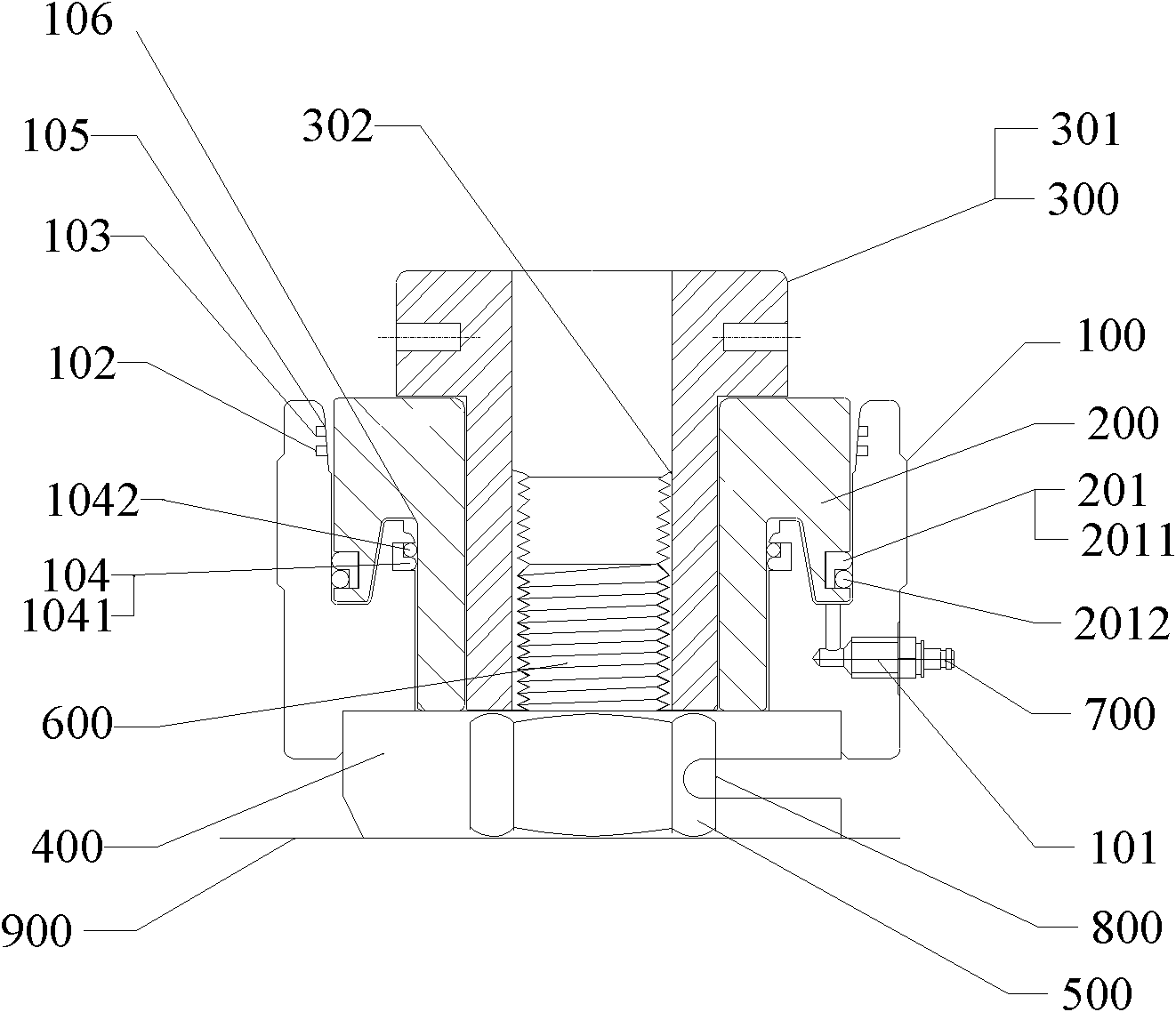
[0004] In order to solve the problems of complex structure and high production cost in the prior art, the present invention provides a hydraulic tensioner with a safety pressure relief device with simple structure, convenient operation, and multiple safety functions of prompting manual pressure relief and automatic pressure relief , the technical solution adopted is:

Method used


Image

  • Hydraulic tensioner with safe pressure relief device

Examples


Embodiment Construction

[0026] The present invention will be further described below in conjunction with the accompanying drawings and embodiments.

[0027] see figure 1 The hydraulic tensioner with a safety pressure relief device of the present invention includes a hydraulic cylinder 100, a piston 200, a tensioning member 300, a support bridge 400, a quick connector 700, and a dial ring 800. The support bridge 400 is arranged on the surface of the connected workpiece 900, The hydraulic cylinder 100 is fixed on the support bridge 400 . The piston 200 is socketed in the hydraulic cylinder 100 , the external structure of the piston 200 matches the internal structure of the hydraulic cylinder 100 , and a through hole is arranged in the center of the piston 200 . The stretching head 301 of the stretching member 300 is arranged on the upper end surface of the piston 200, and the stretching rod 302 is arranged in the through hole of the piston 200. The inner diameter of the stretching rod 302 is adapted t...


PUM


Abstract

The invention relates to a hydraulic tensioner with a safe pressure relief device, comprising a hydraulic oil cylinder, a piston, and a tensioning piece, wherein the piston is arranged in the hydraulic oil cylinder, the tensioning rod of the tensioning piece is arranged in a through hole at the centre of the piston, and is limited via a tensioning head. As one or more limit grooves are arranged on the inner wall close to the top, of the hydraulic oil cylinder, when the pressure in the hydraulic oil cylinder exceeds a set value, a second sealing ring on the piston is pushed to the limit groove, and high-pressure oil overflows via the limit groove, so that the pressure of the oil in the hydraulic oil cylinder is reduced and automatically relieved; and via the plurality of limit grooves, many times of the automatic pressure relief can be realized, so that the hydraulic tensioner is safer and more reliable.

Description

technical field [0001] The invention relates to a hydraulic tensioner, in particular to a hydraulic tensioner with a safety pressure relief device. Background technique [0002] The working principle of the hydraulic tensioner is to inject high-pressure oil into the hydraulic cylinder to push the piston to apply external force to the bolt, so that the applied bolt is elongated in its elastic deformation zone, and the diameter of the bolt is slightly deformed, so that the nut is easy to loosen. Realize the tightening or dismounting of bolts. During the working process, if the pressure in the hydraulic cylinder is too high, it will have adverse effects on the hydraulic tensioner itself and the mechanical parts. [0003] The Chinese Utility Model Patent No. 200720075108.2 discloses a hydraulic tensioner with an overload protection device. The main technology is that the piston is provided with an upper large hole and a lower small hole that communicate with each other and pass...

Claims


Application Information

Patent Timeline
IPC IPC(8): B23P19/06
Inventor 贾纬民慕雷
Owner BEIJING KELU IND EQUIP
Learn More