Spring structure for wheel suspensions in motor vehicles

A technology of spring structure and wheel suspension, applied in the direction of vehicle spring, suspension, elastic suspension, etc., can solve problems such as very crowding and problems

Active Publication Date: 2012-10-31
AUDI AG
View PDF6 Cites 9 Cited by
  • Summary
  • Abstract
  • Description
  • Claims
  • Application Information

AI Technical Summary

Problems solved by technology

However, this reinforcement of the auxiliary frame is problematic due to the tight construction space situation

Method used


Image

  • Spring structure for wheel suspensions in motor vehicles
  • Spring structure for wheel suspensions in motor vehicles
  • Spring structure for wheel suspensions in motor vehicles

Examples


Embodiment Construction

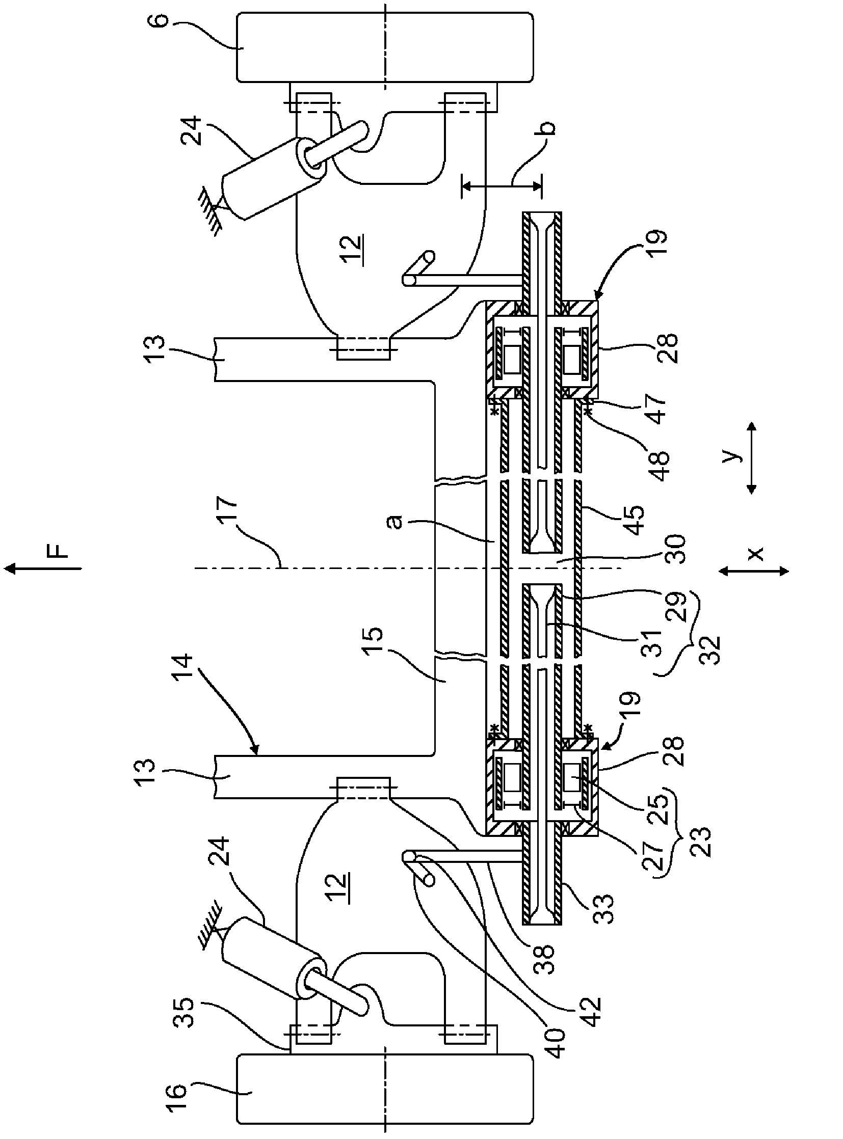
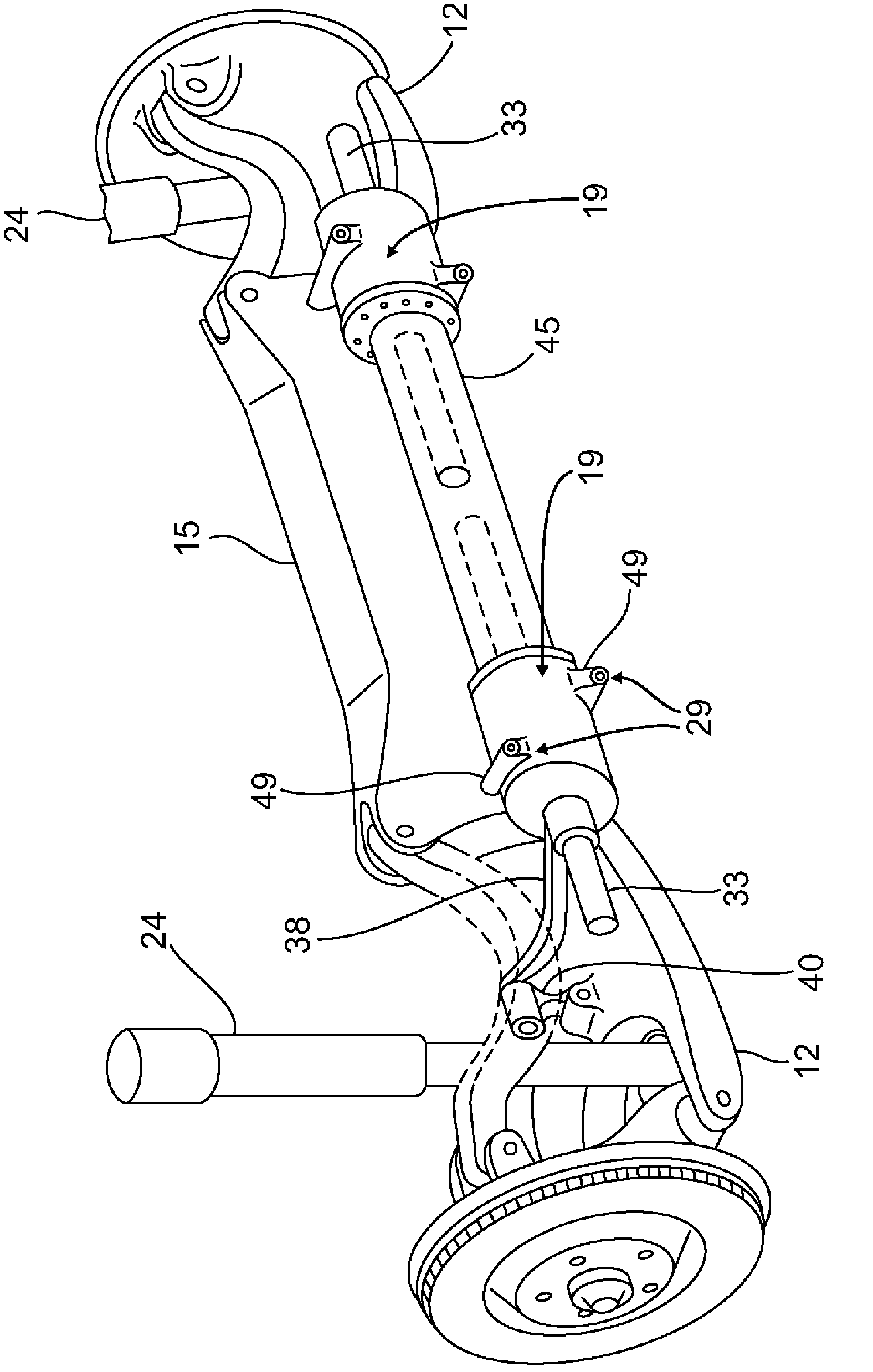
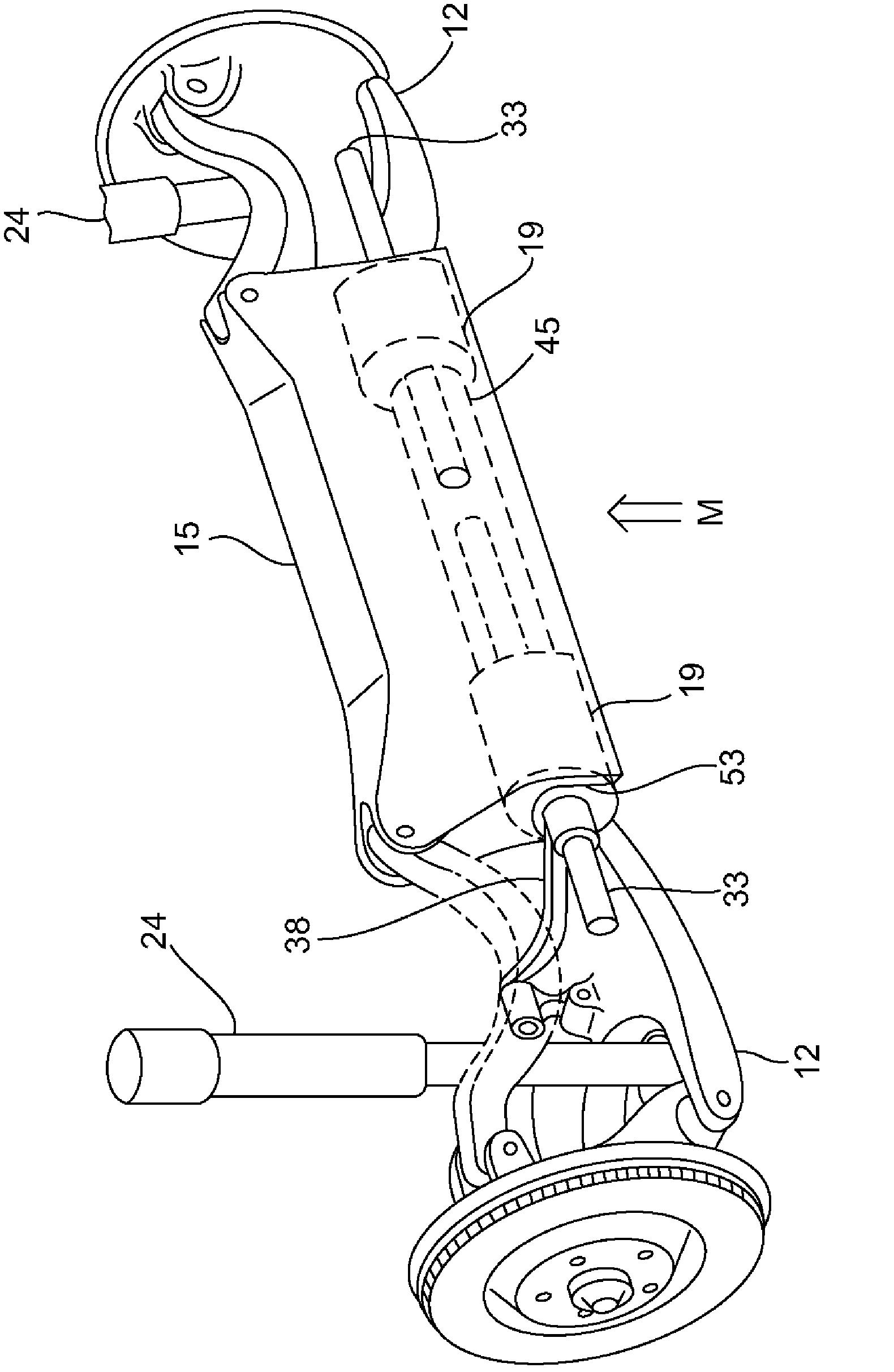
[0020] exist figure 1 The lower planes of the left and right wheel suspensions for the rear axle of a motor vehicle are shown in FIG. On the auxiliary frame 14 and on the other hand is articulated on the schematically shown hub carrier 35 for the rear wheel 16 . The transverse guide arm of the upper part of guiding hub bracket 35 is in figure 1 not visible in the , but only in the figure 2 shown roughly.

[0021] exist figure 1 The wheel suspensions for the left and right rear wheels 16 shown in FIG. figure 1 with 2 not shown in according to figure 1 The subframes 14 each have two lateral side members 13 and a rear cross member 15 in the vehicle longitudinal direction x and are fastened in a manner not shown to the body of the motor vehicle. As already indicated above, the wheel suspensions for the left-hand and right-hand rear wheels are designed mirror-symmetrically with respect to the vehicle center plane 17 .

[0022] If according to figure 1 It follows further ...


PUM


Abstract

The invention provides a spring structure for wheel suspensions in motor vehicles. Each wheel suspension has a rotary actuator (19) with a torsion bar spring (32) running in the vehicle transverse direction (y) and actuatable with an actuator (23). A spring tube (29) is guided transversely inwards vehicle middle. The upper portion of an inner end part of the spring tube is connected with a solid rod (31) in a manner of locking. The solid rod extends transversely outwards in a manner that it is located in the spring tube (29) in the radial direction and works on a wheel guide element (12) of the wheel suspension directly or indirectly through a driven rod (38). Two rotary actuator-housings (28) are connected with each other by a hollow cylindrical connecting support (45). The spring-tubes (29) with the radially inner solid rods (31) of the torsion bar springs (32) of both the rotary actuators (19) extend into a hollow profile (30) of the hollow cylindrical connecting suport.

Description

technical field [0001] The invention relates to a spring arrangement for a wheel suspension of a motor vehicle according to the preamble of claim 1 . Background technique [0002] Such a spring structure is known, for example, from DE 10 2009 005 899 A1. The spring structure has a torsion bar spring actuatable by means of an actuator, which extends in the transverse direction of the vehicle to approximately the transverse center of the vehicle and acts on the wheel side on a drive lever which in turn is hinged to the wheel suspension. on the wheel guide elements of the frame. In DE 102009005899A1, the torsion bar spring is designed in multiple parts and in a nested arrangement, wherein a radially inner solid rod and two radially outer hollow rods made of spring steel are provided, They are connected to one another in a force-transmitting manner, for example by means of rectangular splines. [0003] In the torsion spring system known from DE 10 2009 005 899 A1, spring work...

Claims


Application Information

Patent Timeline
Patent Type & Authority Applications(China)
IPC IPC(8): B60G11/18
CPCB60G2202/42B60G2206/427B60G2204/1222B60G17/025B60G11/183B60G21/0555B60G2202/1351B60G2202/134B60G11/20
Inventor W・迈克尔
Owner AUDI AG
Why Eureka
Try Eureka