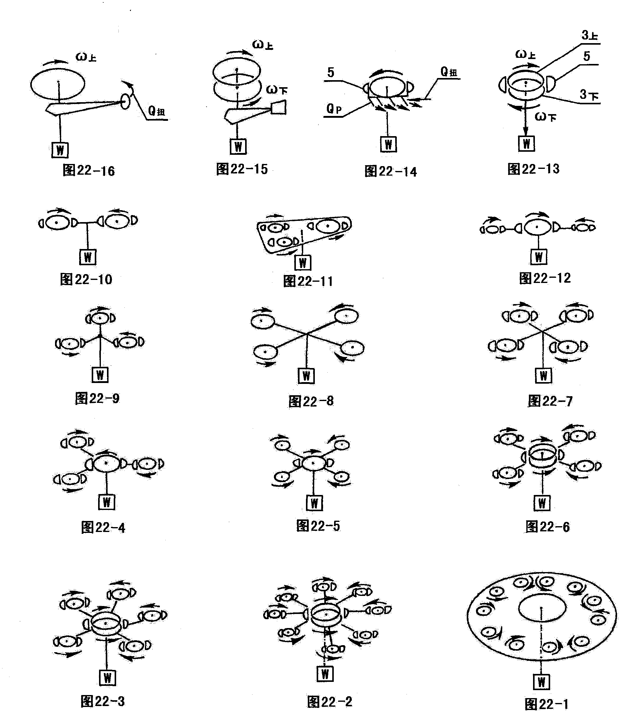
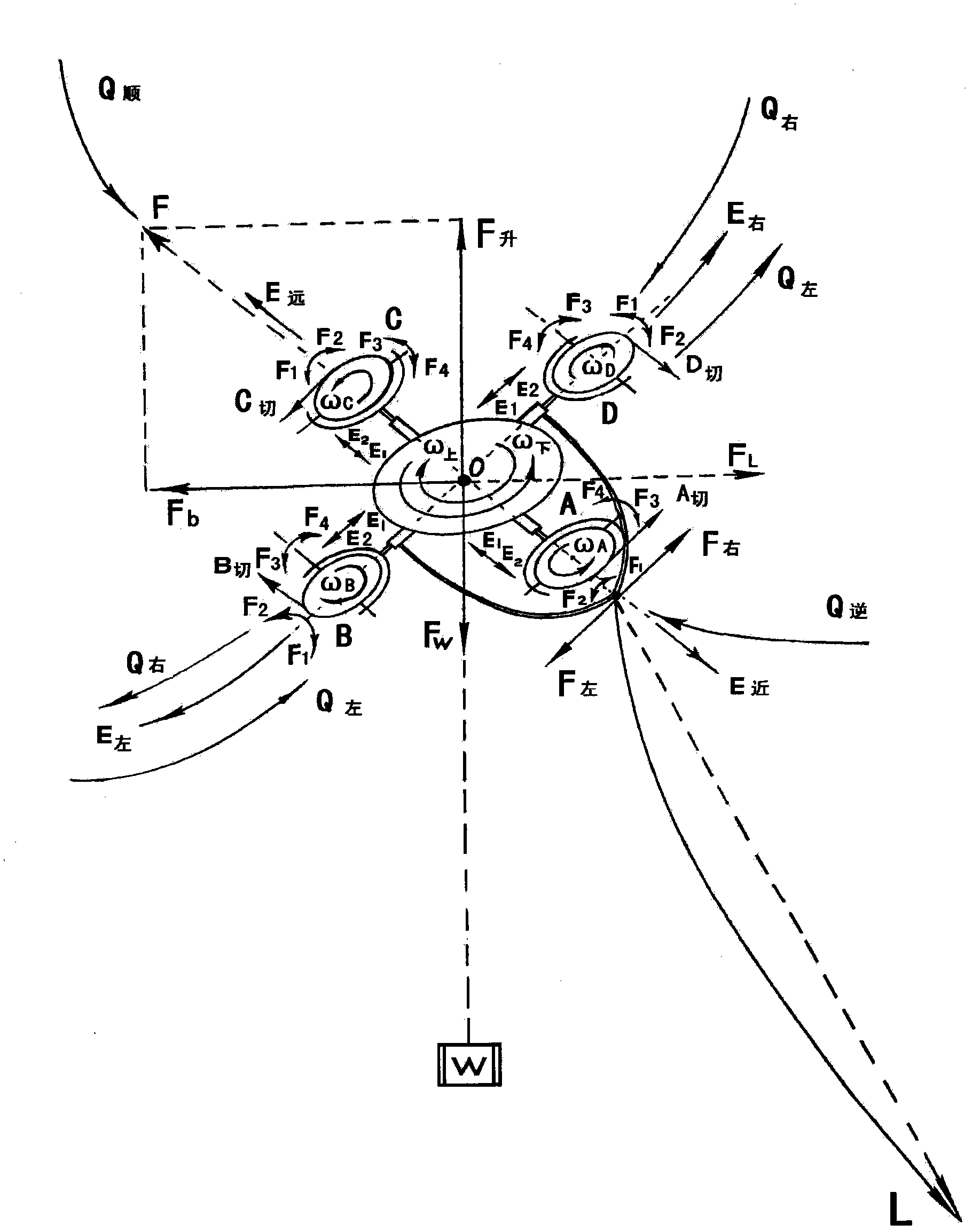
Traction energy transmission type duct rotor wing fly lifter

A flying crane and rotor technology, which is applied in the field of traction energy transmission type ducted rotor flying crane, can solve the problems of not perfecting the gas field of the precursor vortex ring, etc.

Active Publication Date: 2012-10-31
郑鹏
View PDF6 Cites 51 Cited by
  • Summary
  • Abstract
  • Description
  • Claims
  • Application Information

AI Technical Summary

Problems solved by technology

There is no similar rotorcraft that separates the main lift and propulsion aerodynamic structures, and there is no perfect technical method and equipment for actively resisting, interfering, and preventing the eradication of the aerodynamic structure of the vortex ring without avoiding the precursor vortex ring gas field induced by itself

Method used


Image

  • Traction energy transmission type duct rotor wing fly lifter
  • Traction energy transmission type duct rotor wing fly lifter
  • Traction energy transmission type duct rotor wing fly lifter

Examples


Embodiment Construction

[0781] 1. Specific implementation options for the pneumatic mechanism and layout of the flying crane:

[0782] (1). The preferred scheme of the large-diameter main duct rotor body 5 of the flying crane:

[0783] 1. The large-diameter main duct rotor body 5 of the flying hanger looks like a partial drum shape 29, and the body cavity 14 is provided with an annular mouth-shaped main beam 28 between the partial drum-shaped shell 29 and the main duct H1 of the outer ring layer. The inner wall of the large-diameter main duct in the single-ring layer is marked as 11 with the upper and lower linear ring walls. It is preferable to set the inner wall of the outer ring main duct H1 of the double-ring layer main duct as an up and down linear ring inner diameter wall 11, which is combined with the drum-shaped surface of the main culvert body 5 shell 29, and is collectively called the outer ring main duct H1. The main second duct H2 of the inner ring layer is a linear inner diameter wall 2...


PUM


Abstract

The invention relates to a fly lifter, in particular to a duct rotor wing fly lifter mainly used for lifting heavy articles. A pneumatic structure bears the main lifting force by taking a large-diameter main duct coaxial positive and negative rotation dual rotor wing as a center; a variable inertia device is arranged in a rotor wing system, so that the rotor wing system generates differential variable inertia, induces to generate the rigidity of gyroscopic effect and has the capability of resisting turbulence transition wind; a plurality of small-diameter duct rotor wings are arranged outside a multi-ring-layer duct; a connecting arm can do telescopic torsional swing to do four-degree-of-freedom action and bear the auxiliary lifting force, direction and posture control and vortex ring prevention; a main nozzle is arranged at the lower end of the main duct; side nozzles are arranged at the periphery of lower end of the main duct; a swing wind guide plate is inbuilt and used for regulating and controlling direction and performing active type vortex ring prevention; and a plasma energy wave generator is provided and used for performing active type vortex ring prevention and improving Reynolds number. The fly lifter transmits power or fuel in a wireless traction mode and is driven by a power machine with energy to perform wireless remote control, so that the fly lifter has dead wind resistance and high suspended load capacity and can perform durable operation under severe environment and weather conditions.

Description

[technical field] [0001] Utilize the aerodynamic lift of the ducted rotor as the flight equipment for lifting, hoisting, and handling operations required in some fields. [Background technique] [0002] In the field of conventional lifting operations, all kinds of lifting equipment composed of traditional hydraulic truss structure system and movable and fixed pulleys are used. In some areas, many lifting operations are beyond the working range of traditional crane jibs. For example: sea, land, and air long-distance suspended cargo and life-saving operations, etc., generally use large helicopters for long-distance suspended aerial operations. However, there are many restrictions on using a helicopter, and it is very dangerous because the large rotor is not easy to operate in a narrow space. The ability to resist crosswinds, headwinds, and turbulent transitional winds is very limited. It is not easy to hover at low altitude for a long time and take off and land vertically in...

Claims


Application Information

Patent Timeline
Patent Type & Authority Applications(China)
IPC IPC(8): B64C27/20B64D27/16
Inventor 郑鹏
Owner 郑鹏
Why Eureka
Try Eureka