Liquid filling device

A technology of filling device and liquid, applied in liquid distribution, conveying or transfer device, distribution device, special distribution device, etc., can solve the problems of reduced air pressure of liquid sealed container, inconvenient filling of lubricating oil, and reduced filling speed, etc. , to achieve the effect of safe use, improved structure compactness and firmness, and high filling efficiency

Inactive Publication Date: 2012-10-31
HANGZHOU BRANCH ZHEJIANG GEELY AUTOMOBILE RES INST +2
View PDF7 Cites 20 Cited by
  • Summary
  • Abstract
  • Description
  • Claims
  • Application Information

AI Technical Summary

Problems solved by technology

Although this lubricating oil filling device can also realize the filling of liquid or lubricating oil to mechanical equipment; but there are still some defects: 1. At present, there is an air source in the factory workshop, and the air-tight container is filled when the device is used in the workshop Compressed air has the problem of complicated operation. If the liquid sealed container is directly connected to the air source, the problem of unstable filling may be caused by unstable air pressure.
2. After filling the lubricating oil into the liquid-sealed container, the container needs to be sealed again, and there is a problem that it is inconvenient to fill the lubricating oil; at the same time, if the seal is not tight, the air pressure in the liquid-sealed container may decrease and the filling speed will be reduced Can't even achieve a raise

Method used


Image

  • Liquid filling device
  • Liquid filling device
  • Liquid filling device

Examples


Embodiment 1

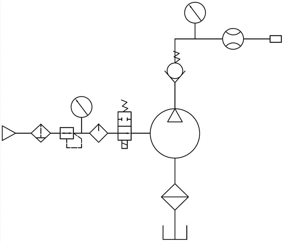
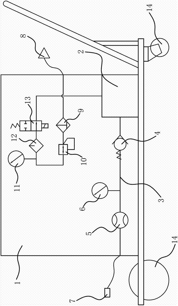
[0034] Such as figure 1 with figure 2 As shown, the liquid filling device includes a liquid storage tank 1, a pneumatic diaphragm pump 2, a filling joint 7 that can communicate with the filling port, and an air intake joint 8 that can communicate with the air supply port. The liquid inlet of the pneumatic diaphragm pump 2 is connected to the liquid storage tank 1 through the liquid inlet pipe assembly and the connection is located at the bottom of the liquid storage tank 1; the liquid outlet of the pneumatic diaphragm pump 2 is connected to the filling joint through the liquid outlet pipe 3 assembly 7 is connected; the air inlet joint 8 is connected with the air inlet of the air-operated diaphragm pump 2 through the air-inlet pipe assembly that can make the gas enter the air-operated diaphragm pump 2 in a stable pressure and can control the air intake or cut-off.

[0035] Specifically, 3 to 4 casters 14 are fixed at the bottom of the liquid storage tank 1; Connected drain v...

Embodiment 2

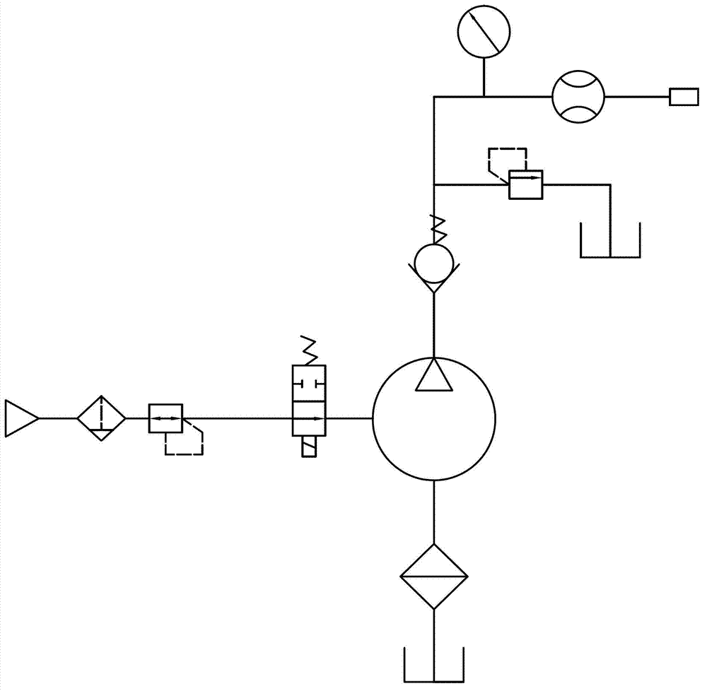
[0040]The structure and principle of this embodiment are basically the same as that of Embodiment 1, the difference is that: image 3 As shown, the liquid outlet pipe 3 assembly includes a liquid outlet pipe 3, a one-way valve 4 and a flow meter 5 connected in series on the liquid outlet pipe 3 in sequence from the liquid outlet of the pneumatic diaphragm pump 2 to the filling joint 7; The outlet pipe 3 is also connected with a liquid pressure gauge 6 and an overflow valve. The one-way valve 4, overflow valve and flowmeter 5 are all fixed on the outer wall of the liquid storage tank 1.

Embodiment 3

[0042] The structure and principle of this embodiment are basically the same as that of Embodiment 1 or Embodiment 2, the difference is that: image 3 As shown, the intake pipe assembly includes an intake pipe, a gas filter 9 , a pressure reducing valve 10 and a control switch 13 connected in series on the intake pipe in sequence from the intake joint 8 to the air inlet of the pneumatic diaphragm pump 2 . The gas filter 9 , pressure reducing valve 10 and control switch 13 are all fixed on the outer wall of the liquid storage tank 1 .


PUM


Abstract

The invention provides a liquid filling device, which belongs to the technical field of operation and solves the problems of complex operation and poor performance existing in the traditional liquid filling device. The liquid filling device comprises a liquid storage box, a pneumatic diaphragm pump, a filling connector which can be communicated with a filling opening and an air inlet connector which can be communicated with an air supply opening, wherein a liquid inlet of the pneumatic diaphragm pump is communicated with the liquid storage box through a liquid inlet pipeline assembly and is positioned at the bottom part of the liquid storage box; a liquid outlet of the pneumatic diaphragm pump is communicated with the filling connector through a liquid outlet pipeline assembly; and the air inlet connector is communicated with an air inlet of the pneumatic diaphragm pump through an air inlet pipeline assembly which can be used for enabling the air to enter into the pneumatic diaphragm pump in voltage stabilization and controlling the air inlet or the air cut. The liquid filling device disclosed by the invention has the advantages of compact structure, convenience for control, high injection efficiency, and time and labor saving; and by adopting the pneumatic diaphragm pump as a power source, the liquid filling device has the advantages of safety in use, stable performance and the like.

Description

technical field [0001] The invention belongs to the field of operation technology, and relates to a liquid storage and transportation device, in particular to a liquid filling device. Background technique [0002] With the rapid development of the world economy, the possession of mechanical equipment is also increasing. Such as mechanical equipment for loading and unloading cargo in large and medium-sized ports; air compressors used in factory workshops or mines, etc. It is essential to carry out daily maintenance on mechanical equipment, which can effectively improve the service life of the equipment. It is a common item to replace lubricating oil or add lubricating oil during maintenance. At present, lubricating oil replacement is mainly manual operation, that is, manually transporting the oil barrel to the work site, and then using the filling barrel to refuel the mechanical equipment. Although this method can realize filling, it is obviously time-consuming and laboriou...

Claims


Application Information

Patent Timeline
Patent Type & Authority Applications(China)
IPC IPC(8): B67D7/00B67D7/76B67D7/36B67D7/56B67D7/06
Inventor 林远利郭琪马芳武杨国斌赵福全
Owner HANGZHOU BRANCH ZHEJIANG GEELY AUTOMOBILE RES INST
Why Eureka
Try Eureka