
LED (Light Emitting Diode) lamp

A technology of LED lamps and LED substrates, applied in the field of LED lamps, can solve problems such as unsatisfactory heat dissipation, affect the life of LED light sources, and affect the normal use of LED lamps, and achieve the effects of improving heat dissipation efficiency, accelerating heat dissipation efficiency, and strengthening heat dissipation effects

Inactive Publication Date: 2012-10-31
OCEANS KING LIGHTING SCI&TECH CO LTD +1
View PDF4 Cites 14 Cited by
  • Summary
  • Abstract
  • Description
  • Claims
  • Application Information

AI Technical Summary

Problems solved by technology

[0002] Sometimes due to the needs of design and light distribution, lamps must use LED light sources, and the number of LED light sources used is large. In this case, the heat dissipation problem of LED lamps is very important. If the heat dissipation problem cannot be solved well, it will inevitably affect Reliability of LED lamps
[0003] When designing the heat dissipation of LED lamps, designers generally add reinforcing ribs directly to the shell of the LED lamp, which can not only achieve the purpose of strengthening the shell of the LED lamp, but also achieve the effect of heat dissipation, but sometimes due to the use of LED lamps When the power of the LED light source is large or the number of LED light sources used is large, such a structure often has an unsatisfactory heat dissipation effect, which will affect the life of the LED light source at the slightest, and make the light efficiency of the LED lamps fail to meet customer requirements and affect the LED lamps. normal use

Method used


Image

  • LED (Light Emitting Diode) lamp
  • LED (Light Emitting Diode) lamp
  • LED (Light Emitting Diode) lamp

Examples


Embodiment Construction

[0019] The specific embodiments of the present invention will be described below mainly in conjunction with the accompanying drawings.

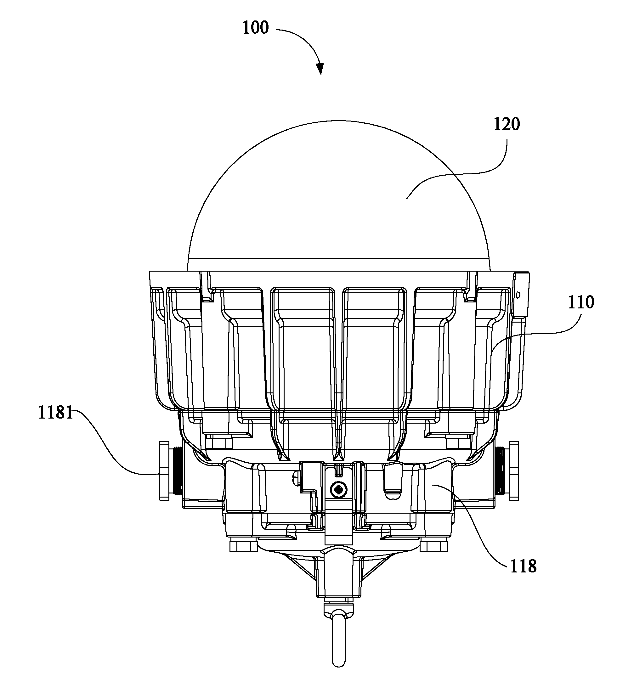
[0020] see figure 1 , the LED lamp 100 of this preferred embodiment includes a lamp holder 110, an LED substrate (not shown in the figure) and a plurality of LED light sources (not shown in the figure). A plurality of LED light sources are fixed on the LED substrate, and the LED substrate is fixed on the lamp holder 110 .

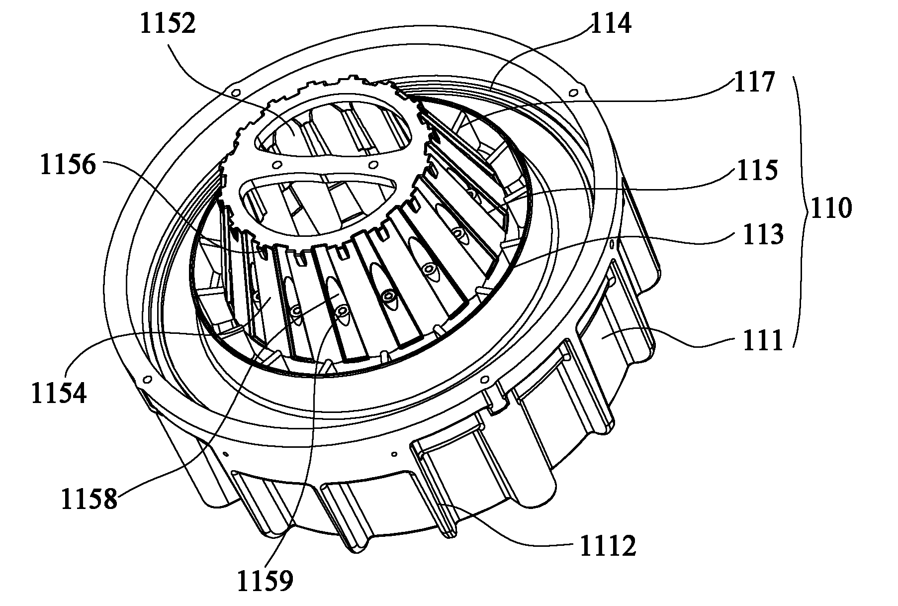
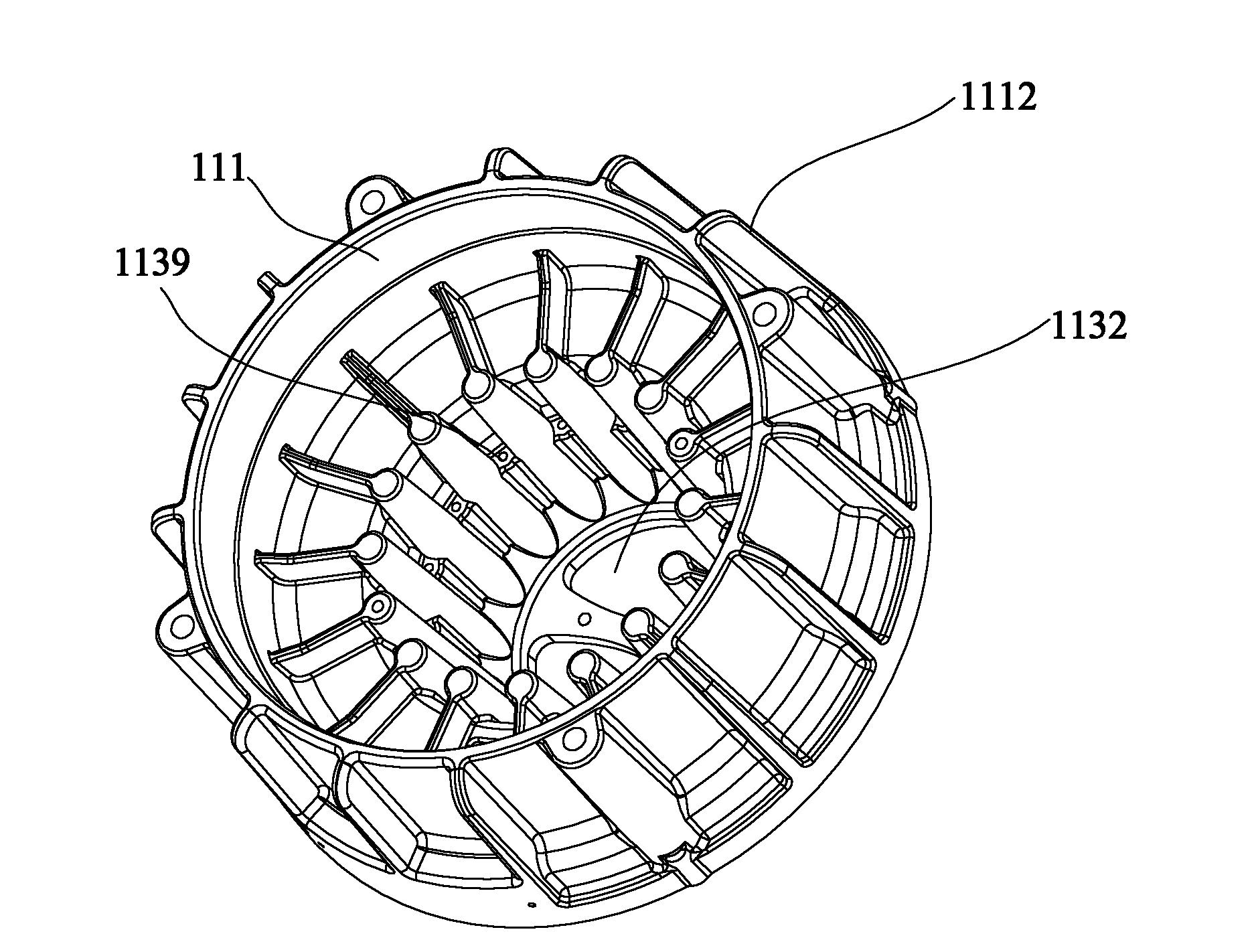
[0021] Please also see figure 2 and image 3 , The lamp holder 110 includes an outer shell 111 , an inner shell 113 and a light source installation stand 115 . The shell 111 is substantially cylindrical and has a plurality of reinforcing ribs 1112 on its outer surface. A plurality of reinforcing ribs 1112 are spaced apart from each other and disposed around the shell 111 . In this preferred embodiment, a plurality of reinforcing ribs 1112 are arc-shaped sheet structures, and are arranged at equal intervals on the out...


PUM


Abstract

The invention discloses an LED (Light Emitting Diode) lamp, which comprises a lamp holder, an LED substrate and a plurality of LED light sources, wherein the LED substrate is fixedly arranged on the lamp holder; the LED light sources are fixedly arranged on the LED substrate; the lamp holder comprises an outer shell, an inner shell in the outer shell and a frustum-shaped light source mounting table of a hollow structure; the light source mounting table is provided with a large end and a small end opposite to the large end; the large end is fixedly arranged in the inner shell; the small end protrudes out of the inner shell; the outer surface of the light source mounting table is provided with a plurality of radiating columns; the LED substrate is fixedly arranged on the radiating columns; the light source mounting table of the LED lamp has the hollow structure; and the LED substrate is fixedly arranged on the radiating columns on the outer surface of the light source mounting table to increase the radiating efficiency of the LED light source.

Description

【Technical field】 [0001] The invention relates to a lighting tool, in particular to an LED lamp. 【Background technique】 [0002] Sometimes due to the needs of design and light distribution, lamps must use LED light sources, and the number of LED light sources used is large. In this case, the heat dissipation problem of LED lamps is very important. If the heat dissipation problem cannot be solved well, it will inevitably affect The reliability of LED lamps. [0003] When designing the heat dissipation of LED lamps, designers generally add reinforcing ribs directly to the shell of the LED lamp, which can not only achieve the purpose of strengthening the shell of the LED lamp, but also achieve the effect of heat dissipation, but sometimes due to the use of LED lamps When the power of the LED light source is large or the number of LED light sources used is large, such a structure often has an unsatisfactory heat dissipation effect, which will affect the life of the LED light so...

Claims


Application Information

Patent Timeline
Patent Type & Authority Applications(China)
IPC IPC(8): F21S2/00F21V17/10F21V29/00F21Y101/02F21V29/503F21V29/77F21V29/83
Inventor 周明杰李秀丽
Owner OCEANS KING LIGHTING SCI&TECH CO LTD
Learn More