Multi-touch and multi-user detecting device

A multi-user detection, multi-point contact technology, used in capacitance measurement, inductance measurement, instruments, etc., can solve problems such as difficult operability, decreased detection accuracy of multi-point detection, and inability to perform multi-point detection, and achieve flexible coordination. Effect

Active Publication Date: 2012-10-31
WACOM CO LTD
View PDF12 Cites 15 Cited by
  • Summary
  • Abstract
  • Description
  • Claims
  • Application Information

AI Technical Summary

Problems solved by technology

[0022] However, in the case of the invention of the pointer detection device using the cross-point electrostatic coupling method described in the above-mentioned Patent Documents 1, 2, etc., it is not considered that multiple users use it at the same time, so although multi-point detection is possible, but cannot determine the user
In addition, in the case of the invention of the multi-user touch system described in the above-mentioned Patent Documents 3 and 4, it is not expected that multiple users use multiple pointing bodies at the same time, so although it is possible to detect users, multi-point detection of each user cannot be performed. (detection of multi-point touch), or cannot perform multi-point detection of each user with high accuracy (detection of multi-point touch)
[0023] First, in the case of the invention of the multi-user touch system described in Patent Document 3, one hand of the user must touch any one of the electrodes EA-ED provided on the table top T100, so it is impossible to use both hands. Operation input
Therefore, it is difficult to consider from the

Method used


Image

  • Multi-touch and multi-user detecting device
  • Multi-touch and multi-user detecting device
  • Multi-touch and multi-user detecting device

Examples


Embodiment Construction

[0044] Hereinafter, one embodiment of the multi-touch multi-user detection device of the present invention will be described with reference to the drawings.

[0045] [Overview of multi-touch and multi-user detection device]

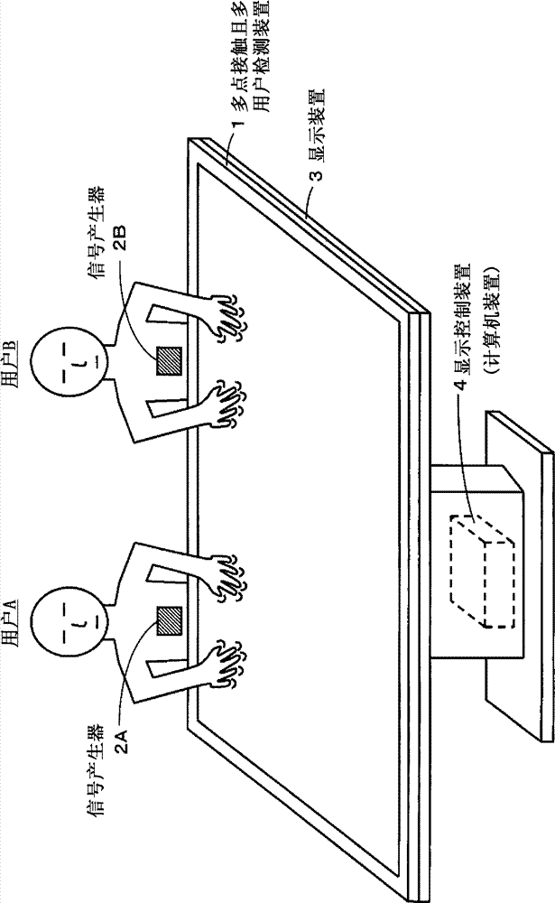
[0046] figure 1 It is a figure for demonstrating the outline|summary of the multi-point-touch multi-user detection apparatus comprised by applying one embodiment of this invention. like figure 1 As shown, the multi-touch and multi-user detection device 1 of this embodiment is stacked on the display screen of the display device 3 and used integrally with the display device 3 .

[0047] That is, the size and shape of the operation surface of the multi-touch and multi-user detection device 1 and the display screen of the display device 3 are substantially the same. Furthermore, the position on the operation surface of the multi-touch and multi-user detection device 1 corresponds to the position on the display screen of the display device 3 in a one-to-o...


PUM


Abstract

A system and method are provided to enable the indication positions of respective indicators (e.g., fingers) to be detected (multiple-point detection) and also to enable detection of the users of the indicators (user detection). Signal generators for generating different signals for respective users are provided, and the signals from the signal generators are supplied to a sensor section through indicators. In a multi-touch and multi-user detecting device 1, a transmitting section 200 supplies determined signals to respective transmitting conductors 11Y. Respective receiving conductors 12X receive the signals from the transmitting conductors 11Y and also the signals from the signal generators of the users. Based on these signals, a user-and-position identifying circuit 33A and a position detecting circuit 34A in a receiving section 300A function to detect indication positions indicated by the respective indicators as well as the users using the indicators.

Description

technical field [0001] The present invention relates to a multi-point contact and multi-user detection device, in order to allow multiple users to simultaneously input information using a plurality of pointers such as pens and fingers, and to detect each position approached or touched by the plurality of pointers for each user . Background technique [0002] Pointer detection devices such as touch panels are widely used, and various inventions related to the pointer detection devices have appeared. The inventors of the present application have previously made an invention related to a pointing body detection device of an intersection type electrostatic coupling method capable of detecting (multipoint detection) a plurality of pointing positions indicated by a plurality of pointing bodies such as fingers, and has been approved by the present application. applicants applied. [0003] Figure 11 The pointer detection device 1X in FIG. 1 shows a configuration example of a poin...

Claims


Application Information

Patent Timeline
IPC IPC(8): G06F3/041
CPCG06F3/0416G06F3/0488G06F3/041G06F2203/04104G06F3/0446G01R27/2605G01R27/2611G06F3/0412G06F3/045G06F3/046
Inventor 小田康雄杉山义久
Owner WACOM CO LTD
Why Eureka
Try Eureka