Logic operation-based distributed feeder automatization fault judgment method

A feeder automation and logic operation technology, applied in fault locations, electrical components, emergency protection circuit devices, etc., can solve the problems of long fault isolation time, small system impact, low equipment service life, etc., to increase the loss of pressure reclosing function, Avoid the effect of influence

Active Publication Date: 2012-10-31
INTEGRATED ELECTRONICS SYST LAB
View PDF4 Cites 19 Cited by
  • Summary
  • Abstract
  • Description
  • Claims
  • Application Information

AI Technical Summary

Problems solved by technology

This type of feeder automation system needs to rely on the setting time difference between the automatic switches and multiple reclosing to isolate the fault. The fault isolation time is long, the system impact is large, and the service life of the equipment is low.
"Surface protection" type feeder automation is a method that relies on the mutual communication between automatic switches and judges to isolate the fault and restore the power supply in a healthy area after a certain logic. It is necessary to re-adjust the equipment parameters

Method used


Image

  • Logic operation-based distributed feeder automatization fault judgment method
  • Logic operation-based distributed feeder automatization fault judgment method
  • Logic operation-based distributed feeder automatization fault judgment method

Examples


Embodiment 1

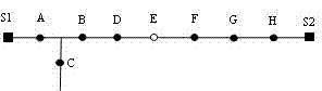
[0033] Such as figure 1 In the distribution network shown, when the system is running in open loop, if a fault occurs in the switch BD section, the switches S1, A, and B experience a fault current, and the switches C and D do not experience a fault current. According to the formulas (1) ~ (5), there are:

[0034] The switch S1 flows through the fault current, and the direction of active power is from the switch to the area S1A, so VN S1 =1, its adjacent switch A experiences a fault current, and the direction of active power flows out of the region S1A, so VN S11 =0, by formula (2) Vgroup S11 ={1&&0}=0, so A S1 =0, switch S1 does not act.

[0035] The fault current flows through switch A, and the direction of active power is to flow out from area S1A and flow into area ABC. So for its first adjacent group, the logical value of switch A VN A is 0, the logic value of switch S1 VN A1 is 1, then its first adjacent switch group Vgroup A1 The value of 0; for...

Embodiment 2

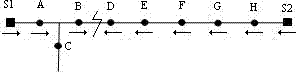
[0042] When the system operates in closed loop, for figure 1 In the distribution network shown, if a fault occurs in the switch BD section, the switches S1, A, B, D, E, F, G, H, and S2 all experience a fault current, and the switch C does not experience a fault current. The fault active power flow direction is as follows: figure 2 Shown:

[0043] The analysis of switches S1, A, and C is exactly the same as that of the open-loop operation, and will not be repeated here.

[0044] Switch B experiences a fault current, for its first adjacent switch group ABC, the logical value of switch A is 1, the logical value of switch B is 0, the logical value of switch C is 1, and the logical value of the first adjacent group Vgroup B1 is 0; for the second adjacent switch group BD, the logic value of switch B VN B is 1, the switch D flows through the fault current, and the direction of active power flows into the interval BD, so its switch logic value VN B1 is 1, so the logical val...

Embodiment 3

[0048] If the system has a temporary fault, after the fault is isolated, the temporary fault will be eliminated. In order to ensure the power supply in the normal area, it is necessary to add the function of reclosing when the switch side loses voltage. In order to ensure the success of the switch reclosing function, the circuit breaker at the outlet of the substation should be equipped with a delay current speed protection function.

[0049] If the fault current is detected again after the switch is reclosed, it means that the fault is a permanent fault, and the switch will be locked in the open state.

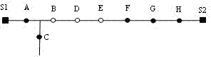
[0050] for figure 1 As shown in the distribution network, when a temporary fault occurs in the BD area, the switch BD will open to isolate the fault, such as image 3 shown. After the switch BD is opened, if the fault is eliminated, switch B detects the loss of voltage on one side, and starts the function of reclosing on one side of the loss of voltage, such as Figure 4 ...


PUM


Abstract

The invention relates to a logic operation-based distributed feeder automatization fault judgment method. The method is characterized in that in combination with the features of a power distribution network, an open-loop operating mode and a closed-loop operating mode of the network adopt a unified fault judgment rule, so as to avoid parameter adjustment due to the changing of operating modes. Through a fixed wire connection manner, the direction of the flow passing through a switch is set, and the flow and fault current passing through the switch are converted into unified analog quantity, and the control state of the switch can be obtained according to the logic operation of adjacent switch groups. A voltage-loss reclosing function on one side of the switch is added, so as to effectively avoid the influence on a grid, which is caused by transient fault. The method is concise, convenient and strong in adaptability, and can meet the actual requirement of feeder automatization.

Description

technical field [0001] The invention relates to the field of distribution network feeder automation, in particular to a logic operation-based distributed feeder automation fault judgment method. Background technique [0002] As an important part of distribution network automation, the feeder automation system has the function of isolating faulty areas and quickly restoring power supply to healthy areas. It is of great significance to reduce the blackout area, shorten the blackout time, and improve the reliability of power supply. Distributed feeder automation system is a method that relies on the mutual cooperation between equipment to isolate faults and restore power to healthy areas. According to the way of fault isolation, it can be divided into switch coordination type feeder automation and "surface protection" type feeder automation. Switch-coordinated feeder automation does not require communication, relying only on the mutual cooperation between automated switches ...

Claims


Application Information

Patent Timeline
Patent Type & Authority Applications(China)
IPC IPC(8): H02H7/26G01R31/08
Inventor 张伟
Owner INTEGRATED ELECTRONICS SYST LAB
Why Eureka
Try Eureka