Roller for in-furnace conveyance

A technology of fitting parts and parts, applied in furnaces, roller tables, furnace types, etc., can solve the problems of large strain and stress of welding parts, easy damage of welding parts, etc., and achieve the effect of relieving strain and stress

Inactive Publication Date: 2012-10-31
IHI CORP
View PDF14 Cites 0 Cited by
  • Summary
  • Abstract
  • Description
  • Claims
  • Application Information

AI Technical Summary

Problems solved by technology

As a result, the deformation of the welded portion is restrained due to the nearby fitting, so large strain and stress are generated in the welded portion, and the welded portion becomes easily damaged.

Method used


Image

  • Roller for in-furnace conveyance
  • Roller for in-furnace conveyance
  • Roller for in-furnace conveyance

Examples


no. 1 approach )

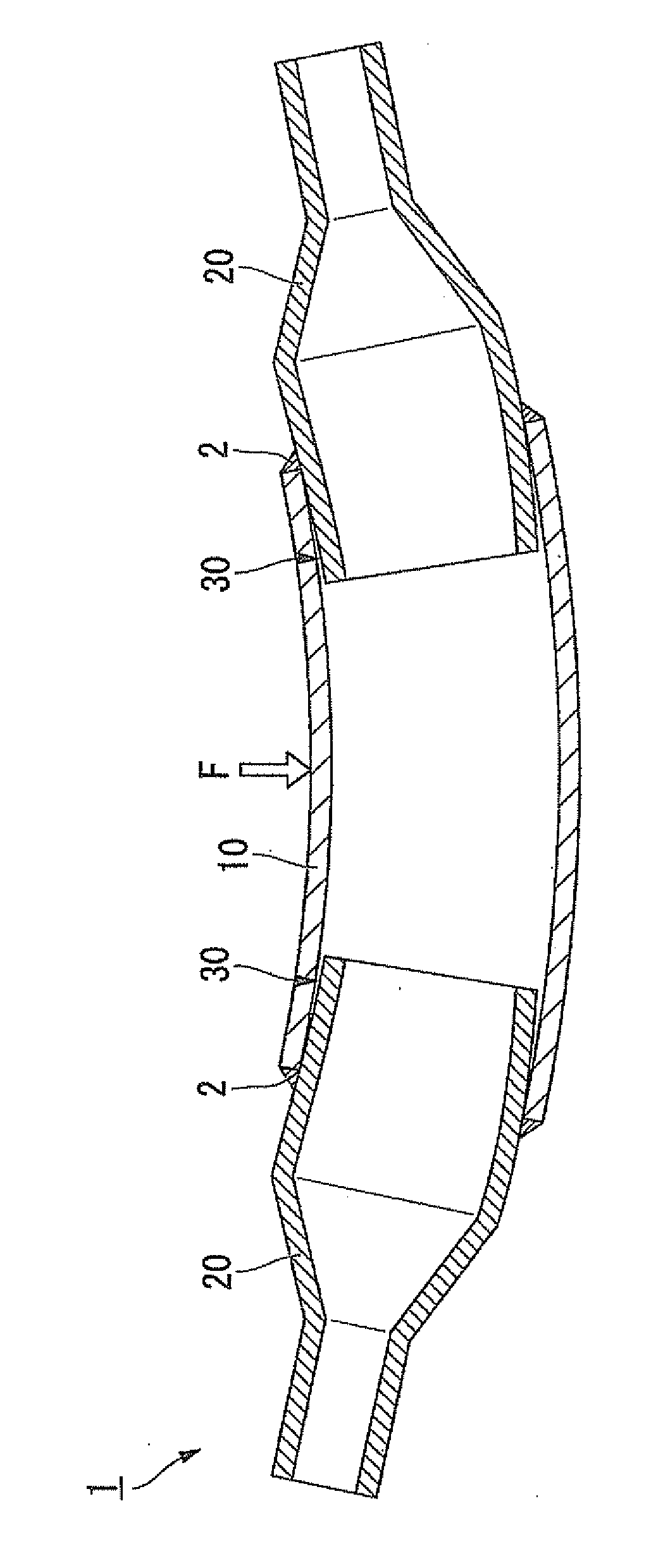
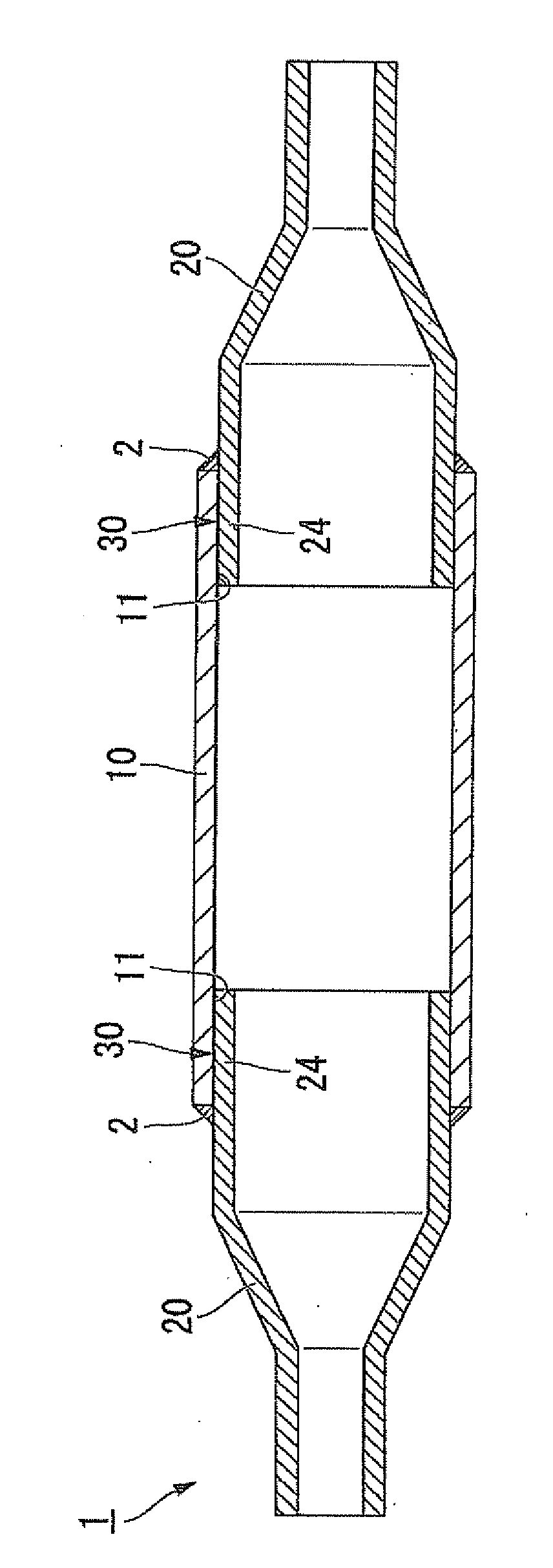
[0035] figure 1 It is a sectional view showing the roller 1 for in-furnace conveyance which concerns on 1st Embodiment of this invention. figure 2 It is an exploded view showing components of the roller 1 for conveying in a furnace according to the first embodiment of the present invention.

[0036] The roller 1 for in-furnace conveyance is comprised from two or more structural members, and a single roller is comprised by welding. The in-furnace conveying roll 1 is installed in a heating furnace for heating a metal workpiece at a high temperature for a long time for heat treatment or hot rolling. The roller 1 for in-furnace conveyance has a main body (first component) 10 that conveys a metal workpiece at the center of the furnace, and rotating shafts (second component) 20 welded to both ends of the main body 10 .

[0037] The main body part 10 is exposed to high temperature since it is disposed in the central region of the furnace, and is made of a material having a lower c...

no. 2 approach )

[0051] Next, a second embodiment of the present invention will be described. In the following description, the same reference numerals are assigned to the same or equivalent components as those in the above-mentioned embodiment, and the description thereof will be simplified or omitted.

[0052] Figure 4 It is a cross-sectional view showing a combined portion of the rotating shaft portion 20 and the rotating shaft body 40 of the roller 1 for in-furnace conveyance according to the second embodiment of the present invention. Figure 5 yes Figure 4 A magnified view of region A is shown.

[0053] The roller 1 for in-furnace conveyance has the rotating shaft body (2nd structural member) 40 welded to the rotating shaft part (1st structural member) 20. At the end of the small-diameter portion 23 of the rotating shaft portion 20 , a fitting hole 23 a having a two-stage structure fitted with the rotating shaft body 40 is provided.

[0054] The rotating shaft body 40 is pivotally ...

no. 3 approach )

[0063] Next, a third embodiment of the present invention will be described. In the following description, the same reference numerals are assigned to the same or equivalent components as those in the above-mentioned embodiment, and the description thereof will be simplified or omitted.

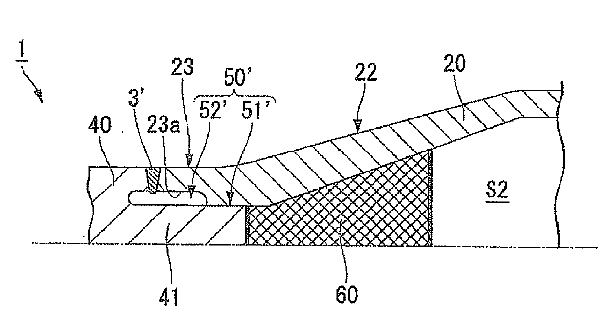
[0064] Figure 6 It is an enlarged cross-sectional view showing a combined portion of the rotating shaft portion 20 and the rotating shaft body 40 of the roller 1 for conveyance in a furnace according to the third embodiment of the present invention.

[0065] Such as Figure 6 As shown, the fitting part 50' formed by fitting the fitting hole 23a of the rotating shaft part 20 and the fitting shaft 41 of the rotating shaft shaft body 40 is connected via the welding part 3'. The fitting part 50' has: a first fitting part 51' fitted with a predetermined gap at a position away from the position where the welded part 3' is formed (welding position); The fitting part 51' fits the second fitting pa...


PUM


Abstract

A roller (1) for in-furnace conveyance is provided with engagement sections (30) at each of which an engagement hole (11) of a barrel section (10) and an engagement shaft (24) of a shaft section (20) are engaged with each other, and the roller is formed as a single roller by welding the engagement sections (30). The engagement sections are each provided with: a first engagement section (31) at which the engagement hole (11) and the engagement shaft (24) are engaged with each other at a position separated from the position of the weld with a predetermined gap provided therebetween; and a second engagement section (32) at which the engagement hole (11) and the engagement shaft (24) are engaged with each other at a position adjacent to the position of the weld with a gap provided therebetween, the gap being greater than that of the first engagement section.

Description

technical field [0001] The present invention relates to a roller for conveying in a furnace. This application claims priority based on Japanese Patent Application No. 2010-042432 for which it applied in Japan on February 26, 2010, and uses the content here. Background technique [0002] Patent Document 1 discloses an in-furnace conveying roll installed in a heating furnace for heating a metal workpiece at a high temperature for a long time for heat treatment or hot rolling. In this roller for in-furnace conveyance, the roller materials respectively produced as the central main body part and the other part are fitted and welded to each other, and the whole roller is comprised. According to this configuration, the main body part disposed in the center of the furnace and exposed to high temperature is made of an expensive material with a small linear expansion coefficient, and the rotating shaft part located in the furnace wall part and disposed in a region lower than the furn...

Claims


Application Information

Patent Timeline
Patent Type & Authority Applications(China)
IPC IPC(8): C21D1/00F27B9/24
CPCF27B9/24C21D9/00F27D3/026F27B9/2407B65G13/00C21D1/00Y10T29/49549Y10T29/49556
Inventor 山冈弘人山下洋一米山夏树口诚宽本城恒
Owner IHI CORP
Why Eureka
Try Eureka