

Forklift
a forklift and seat technology, applied in the field of forklifts, can solve problems such as no driver protection
- Summary
- Abstract
- Description
- Claims
- Application Information
AI Technical Summary
Benefits of technology
Problems solved by technology
Method used
Image

Examples
Embodiment Construction
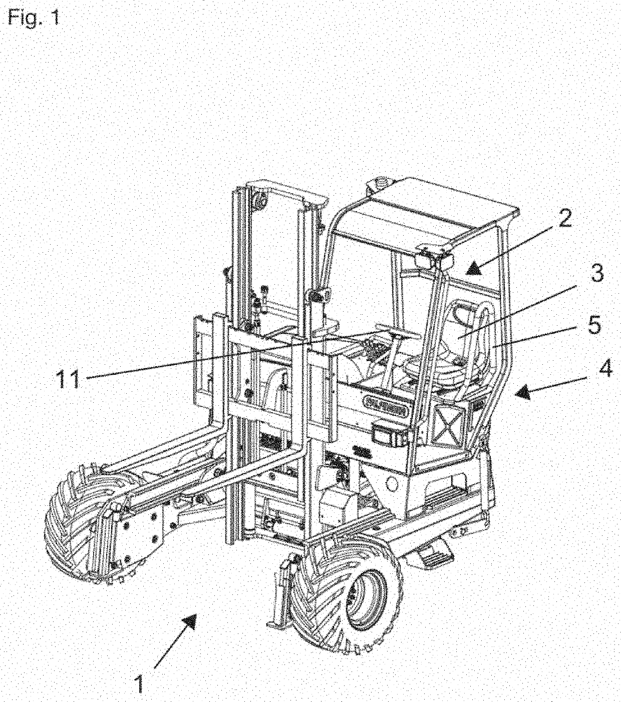
[0026]The figures show a truck-mounted forklift 1 having a cabin 2 and a seat 3 for use by a driver arranged in the cabin 2.
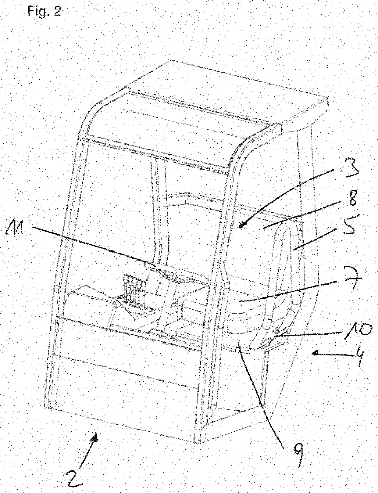
[0027]The cabin 2 has a lateral opening 4 to enter and exit the cabin 2. The seat 3 is mounted rotatably relative to the cabin 2.
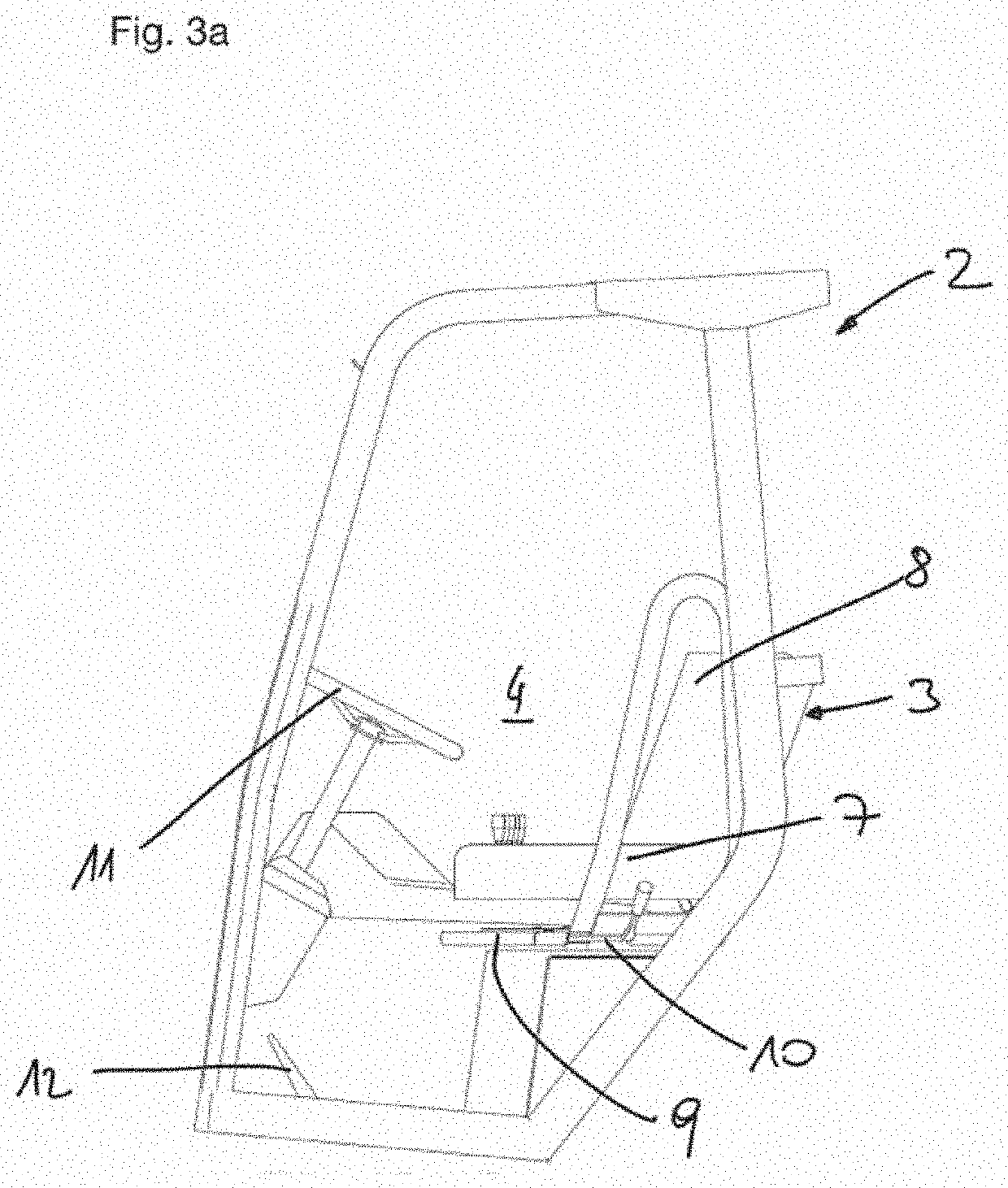
[0028]There is provided a safety bracket 5 for preventing a driver from involuntarily exiting the cabin 2 through the lateral opening 4 and for providing lateral impact protection. According to the invention the safety bracket 5 is mechanically connected to the seat 3 to be rotatable together with the seat 3. The safety bracket 5 can be used as a handgrab by the driver when entering the cabin 2.
[0029]The safety bracket 5 rotates together with the seat 3 in an upright position. The safety bracket 5 extends from the sitting surface 7 of the seat 3, or more specifically from the seat mounting frame 9 under the seat 3, to an upper end of the backrest 8 of the seat 3 and in the shown embodiment extends for a distance beyond the upper end o...
PUM
 Abstract
Description
Claims
Application Information