Automotive door latch device

A technology for door locks and automobiles, applied to vehicle locks, devices for fastening carpets, doors, etc., to achieve the effects of preventing abnormal noise, improving freedom, and improving discharge efficiency

Active Publication Date: 2012-10-31
AISIN SEIKI KK
View PDF6 Cites 16 Cited by
  • Summary
  • Abstract
  • Description
  • Claims
  • Application Information

AI Technical Summary

Problems solved by technology

Therefore, due to the presence of the pawl return spring, the discharge of dust, etc., that has invaded into the storage portion (space) of the lock body that accommodates the lock piece and the pawl is hindered from being discharged to the outside of the lock, resulting in the above-mentioned storage portion (space). piled up worries

Method used


Image

  • Automotive door latch device
  • Automotive door latch device
  • Automotive door latch device

Examples


Embodiment Construction

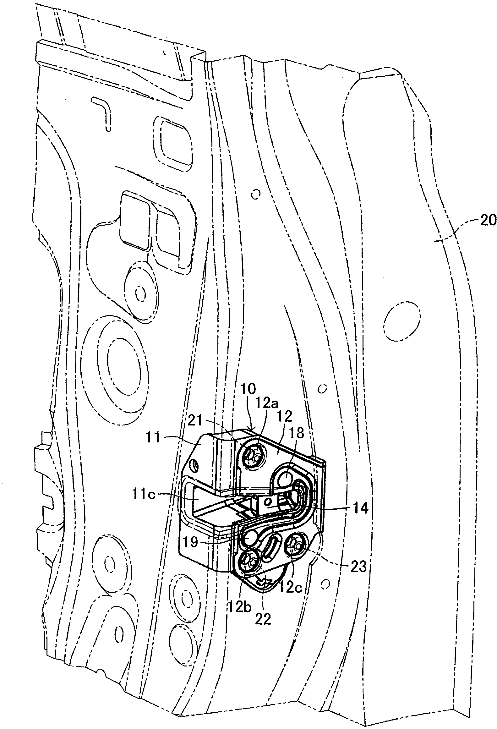
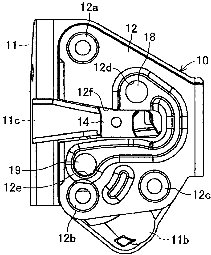
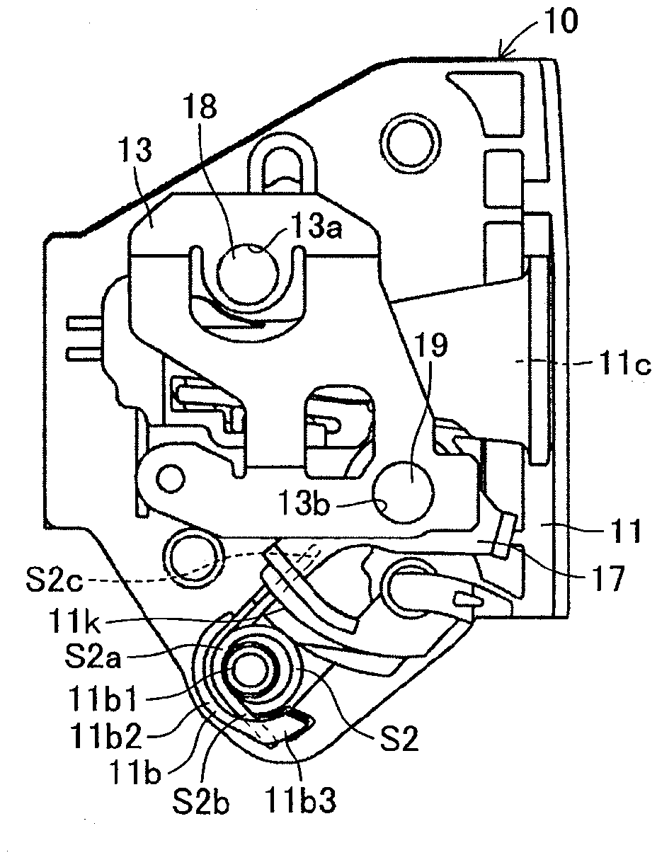
[0037] Hereinafter, each embodiment of the present invention will be described based on the drawings. Figure 1 to Figure 5 One embodiment (first embodiment) of the automobile door lock device according to the present invention is shown. The automobile door lock device 10 of this embodiment is mounted on the front right side of the automobile together with the vehicle door lock device (not shown). The door 20 of side equipment (refer to figure 1 The device of the imaginary line), which has: a lock body 11 made of resin; a base plate 12 made of steel; S1; pawl 15 made of metal; pawl return spring S2 made of spring steel; stopper 16 made of rubber and lift lever 17 made of steel plate (made of metal).

[0038] Such as Figure 5 ~ Figure 10 As shown, the lock body 11 is formed with a storage portion 11a1 for accommodating the locking piece 14 and the pawl 15 on one side of the vertical wall W sandwiched between the base plate 12 and the sub-base plate 13 (the side where the bas...


PUM


Abstract

An automotive door latch device is provided with a latch which rotates by being pushed into motion by a striker; a latch return spring which applies force to the latch in the direction of the return position; a pawl which engages with the latch and prevents the same from rotating in the door opening direction (in the direction of the return position); and a pawl return spring which applies force to the pawl in the direction of the return position. A housing section, which belongs to the body and houses the latch and the pawl, opens downward at a location which is at one side of the body and is below the pawl. A pawl return spring is mounted on a spring mounting section formed at a location which is at the other side of the body and is away and downward from the rotation support section of the pawl. The pawl side end of the pawl return spring engages with the pawl via a through hole provided in the body. Due to the above, it is possible to enhance the discharging of powder dust or the like intruding inside the housing section, which belongs to the body and houses the latch and the pawl, outside the body.

Description

technical field [0001] The present invention relates to a door lock device for automobiles. Background technique [0002] As a kind of door lock device for automobiles, there is a door lock device for automobiles in which a lock plate suitable for being pushed and rotated by a striker on the side of the lock body is accommodated in a storage portion formed on one side of the lock body, and is passed through a second lock body. A support shaft is rotatably supported on a base plate, and the base plate is suitably arranged to cover the storage portion of the lock body on one side and assembled to the door, and is biased toward the return position of the lock plate by a lock piece return spring. The pawl, which engages with the locking piece to prevent the locking piece from rotating in the door opening direction, is accommodated in the housing portion of the lock body under the locking piece and is rotatably supported on the base plate via the second support shaft. , and a pa...

Claims


Application Information

Patent Timeline
Patent Type & Authority Applications(China)
IPC IPC(8): E05B65/32B60J5/00
CPCE05B2015/041E05B85/26E05B85/02E05B77/34Y10S292/23Y10T292/1047Y10T292/1082
Inventor 秋月龙次郎西尾贵士渡边颂子园靖彦小岛一记
Owner AISIN SEIKI KK
Why Eureka
Try Eureka