Pulse valve for bag type dust collector and connecting structure and connecting method of pulse valve

A bag filter and pulse valve technology, applied in chemical instruments and methods, separation methods, dispersed particle separation, etc., can solve the problems of inconvenient use of wrenches or pipe wrenches, high installation size requirements, and inconvenient maintenance.

Inactive Publication Date: 2014-09-10
许学龙
View PDF5 Cites 0 Cited by
  • Summary
  • Abstract
  • Description
  • Claims
  • Application Information

AI Technical Summary

Problems solved by technology

However, there are multiple such connected pulse valves arranged in the field, and the distance between the pulse valves and the various pipelines is relatively short, so it is very inconvenient to use a wrench or pipe wrench
[0013] (3) During installation, it is necessary to consider the direction alignment of the injection port of the pulse valve, and also consider the insertion depth of the connecting pipe, etc. The requirements for the installation size are high and time-consuming
During actual operation, air leakage often occurs due to improper insertion of the inlet end and outlet end of the connecting pipe 30, and it takes a lot of time to adjust the insertion degree
[0014] (4) In the state where the wall-piercing pipe 70 is fixed to the wall plate a according to the flange 71, the sealing flat nut 81 and the sealing sheet 82, when tools such as a wrench or a pipe wrench are used to tighten the second compression nut 41, it is possible Loosen the state where the through-wall pipe 70 is fixed to the wall plate a
[0017] (2) Two workers are required to cooperate with the installation. If the pipe on one side is installed, it will be more difficult to install on the other side
Some companies even weld the pulse valve directly on the wall of the dust collector and the gas bag after connecting the pulse valve to the pipeline, which is not conducive to repair and maintenance.
Moreover, there are processes such as repeated alignment, repeated tightening, repeated distance adjustment, and repeated calibration, which are time-consuming
[0018] (3) It is very difficult to load and unload, and it is very inconvenient to maintain

Method used


Image

  • Pulse valve for bag type dust collector and connecting structure and connecting method of pulse valve
  • Pulse valve for bag type dust collector and connecting structure and connecting method of pulse valve
  • Pulse valve for bag type dust collector and connecting structure and connecting method of pulse valve

Examples


Embodiment Construction

[0054] Hereinafter, embodiments of the present invention will be described in detail with reference to the drawings. For ease of description, according to the flow direction of the compressed gas, the two ends of each component are respectively described as an inlet end and an outlet end. Moreover, words such as "first", "second", and "third" described below are only for convenience of description, that is, additional words to distinguish parts with the same name, and are not used to limit the scope of protection. .

[0055] First, the case of using the male thread pulse valve of the present invention will be described.

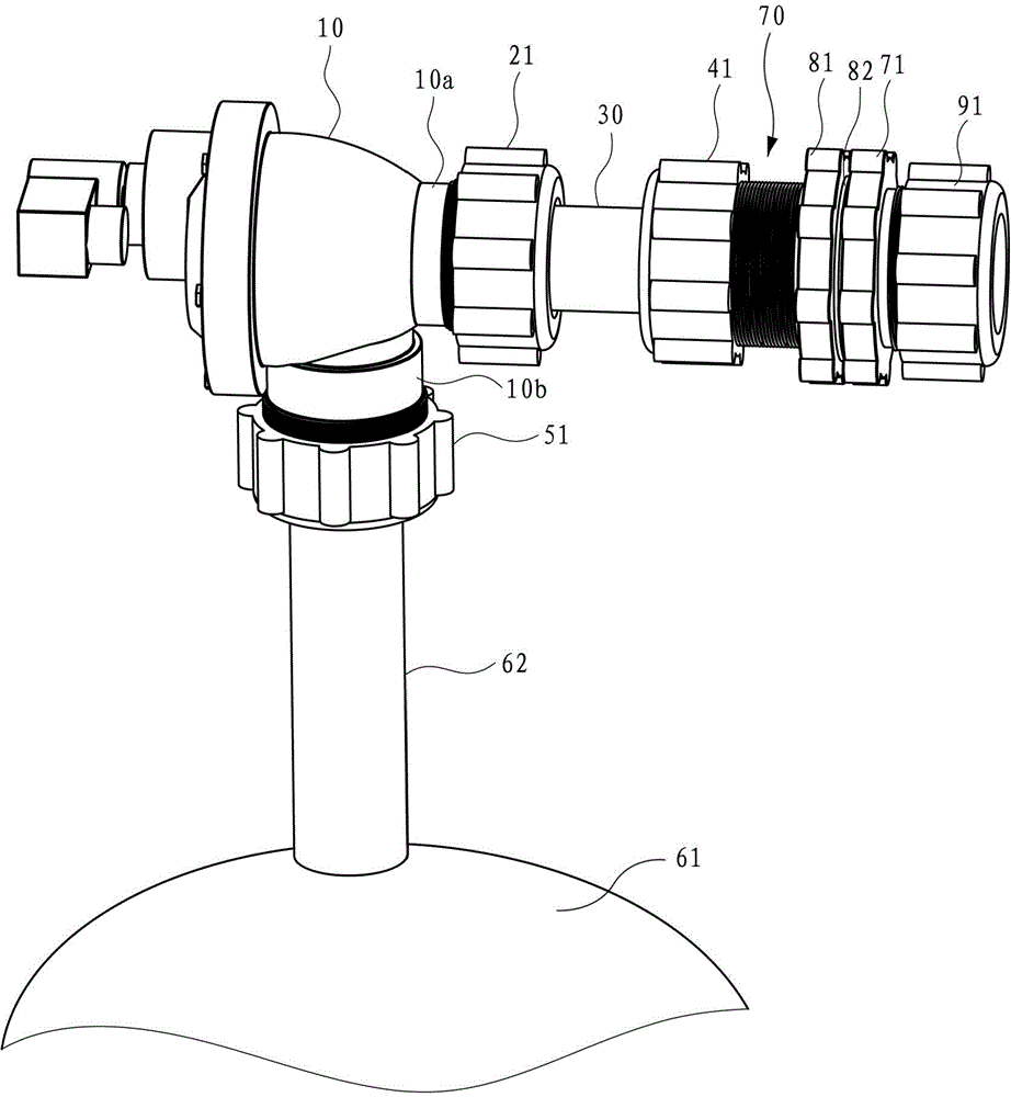
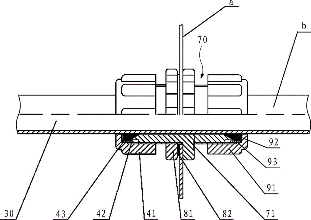
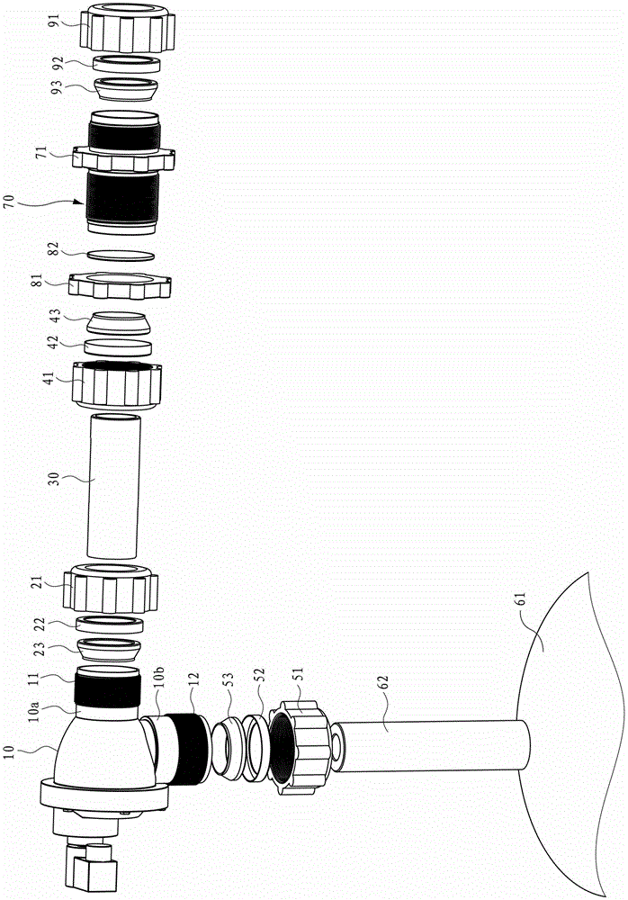
[0056] Such as Figure 5 As shown, the connection structure of the externally threaded pulse valve of the present invention is as follows. The air outlet pipe 110 of the externally threaded pulse valve 100 is sealingly plugged and connected to the inlet end of the wall-piercing pipe 300 . At this time, the first compression nut 210 can be sealingly inserte...


PUM


Abstract

The invention discloses a pulse valve for a bag type dust collector and a connecting structure and a connecting method of the pulse valve. The pulse valve is an external thread type pulse valve and is characterized by comprising an air outlet pipe provided with an external thread and an air inlet pipe provided with an external thread, wherein the air outlet pipe is hermetically inserted into and connected with the air inlet end of a wall penetrating pipe, and the air outlet end of the wall penetrating pipe is connected with the air inlet end of a blowing pipe for guiding compressed air to a filter bag in a sealing mode; and a concave part is formed on the end face of the air inlet pipe, the concave part is matched with a convex part formed by upward protrusion of the inner circumference of a butting pipe so that the air inlet pipe is butted to the air outlet end of the butting pipe in the sealing mode, and the air inlet end of the butting pipe receives the compressed air in an air pocket.

Description

technical field [0001] The invention relates to a pulse valve and its connection structure and connection method, in particular to a pulse valve used for a bag filter and its connection structure and connection method. Background technique [0002] The bag filter is a dust removal device that uses a dust bag made of fiber woven fabric to capture solid particles in a dusty gas. When the dusty gas passes through the dust collector, the dust adheres to the outer surface of the filter bag, settles down due to the action of gravity, and falls into the ash hopper, while the clean gas enters the inside of the filter bag through the filter material. With the accumulation of dust on the surface of the filter bag, the efficiency and resistance of the dust collector will increase accordingly. When the pressure difference on both sides of the filter bag is large, the efficiency of the dust collector will decrease. Besides, the high resistance power will dramatically lower air volume of...

Claims


Application Information

Patent Timeline
Patent Type & Authority Patents(China)
IPC IPC(8): B01D46/04B01D46/42
CPCB01D46/02B01D46/04B01D46/42B01D46/48
Inventor 许学龙江永跃许慧雯
Owner 许学龙
Why Eureka
Try Eureka