Automatic centering fixture for workpiece with revolution boss and/or hole

An automatic centering and workpiece technology, applied in the direction of metal processing machinery parts, clamping, positioning devices, etc., can solve the problems of inability to adjust, difficult to ensure accurate centering, poor flexibility, etc., to achieve reliable locking, reduce centering and Locking workload and time, accurate centering effect

Active Publication Date: 2012-11-07
JIANGSU GAOJING MECHANICAL & ELECTRICAL EQUIPMENT CO LTD
View PDF7 Cites 27 Cited by
  • Summary
  • Abstract
  • Description
  • Claims
  • Application Information

AI Technical Summary

Problems solved by technology

However, this positioning fixture needs to be threaded on the workpiece to be clamped before clamping, so as to fix the positioning member on the workpiece, and the process is complicated
The fixture is only positioned and clamped for one type of workpiece, and cannot be adjusted ac

Method used


Image

  • Automatic centering fixture for workpiece with revolution boss and/or hole
  • Automatic centering fixture for workpiece with revolution boss and/or hole
  • Automatic centering fixture for workpiece with revolution boss and/or hole

Examples


Embodiment Construction

[0040] The present invention will be described in detail below with reference to the accompanying drawings and specific embodiments.

[0041] In this embodiment, a workpiece with a cylindrical boss and a circular through hole is taken as an example for illustration. The workpiece can be clamped internally from the inside of the through hole, or centered from the outer contour of the cylindrical boss. . However, the present invention is not limited to the above-mentioned workpieces, and can also be of other types, as long as they have a rotary boss or an inner hole (such as a rotary inner hole, preferably a through hole).

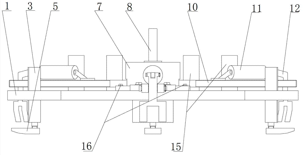
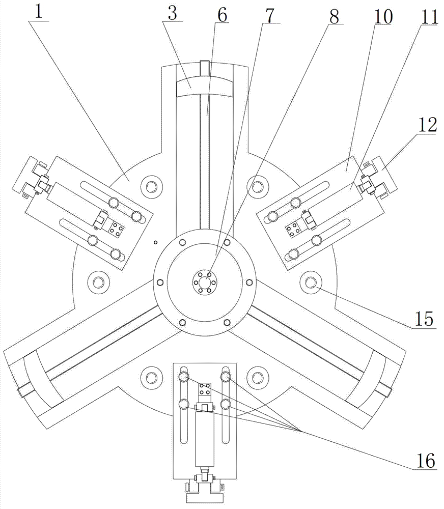
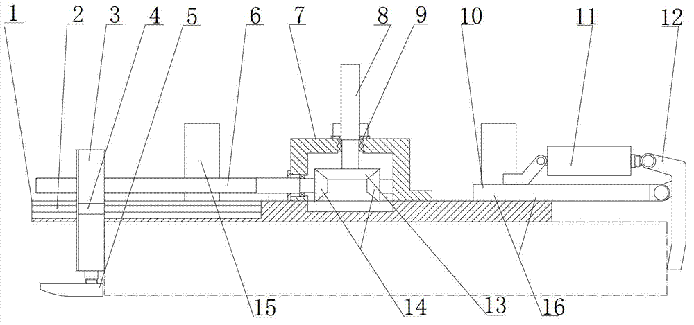
[0042] like Figure 1-3 , The self-centering fixture in this embodiment includes a chassis 1, a guide rail 2, a centering drive device, 3 self-centering slides, an internal clamping device and an external clamping device.

[0043] There are multiple sets of guide rails 2, which are evenly distributed radially and installed on the chassis 1. In this embodim...


PUM


Abstract

The invention discloses an automatic centering fixture which comprises a base plate, at least one internal clamping device, at least one external clamp and a centering drive device, wherein a plurality of guide rails are radically and uniformly arranged on the base plate; an automatic centering slide block is arranged on each guide rail in a sliding manner; each internal clamping device is fixed on the corresponding automatic centering slide block so as to achieve the centering effect through tightly clamping the workpiece from an inner hole or propping against the workpiece from the outer outline of a revolution boss; the external clamps are radically mounted on the base plate so as to clamp the workpiece from the outer outline of the revolution boss; and the centering drive device is used for driving the automatic centering slide blocks to slide along the guide rails, so as to enable the internal clamping devices to be suitable for inner holes with different diameters and to achieve the clamping of the workpieces. Due to the adoption of the fixture provided by the invention, the workload and time for clamping and centering the workpiece with the revolution boss and/or the hole are greatly reduced, and the centering is accurate and the clamping is reliable.

Description

technical field [0001] The invention relates to the field of clamps in mechanical cutting, in particular to a clamp for automatic centering and locking of parts with rotary bosses or rotary holes. Background technique: [0002] In mechanical cutting, in order to ensure the machining accuracy of the workpiece, there must be accurate positioning between the processing machine tool and the workpiece, that is, the precise clamping and positioning of the workpiece is an important factor to ensure the machining accuracy. Especially for parts with revolving bosses and / or revolving holes, such as large-scale revolving parts, etc., it is usually necessary to perform axis positioning during processing, and to perform multiple clamping and positioning. The selection of clamping fixtures for such parts Very important. [0003] At present, there is no special fixture for the positioning between the on-site processing machine tool and large parts. Generally, it is the fixture that comes ...

Claims


Application Information

Patent Timeline
IPC IPC(8): B23Q3/12
Inventor 郑金来姜昕亚沈大为邵新宇崔海斌喻道远吴胜龚文明周伯华张三强
Owner JIANGSU GAOJING MECHANICAL & ELECTRICAL EQUIPMENT CO LTD
Why Eureka
Try Eureka