Pulley assembly and crane

A technology of pulley components and cranes, which is applied in the direction of load hanging components, transportation and packaging, etc., which can solve the problems of flexible cables that cannot be used normally, and achieve the effects of reducing labor intensity and avoiding danger

Inactive Publication Date: 2012-11-07
上海敏坚实业有限公司
View PDF9 Cites 6 Cited by
  • Summary
  • Abstract
  • Description
  • Claims
  • Application Information

AI Technical Summary

Problems solved by technology

Tangled wire won't work properly

Method used


Image

  • Pulley assembly and crane
  • Pulley assembly and crane
  • Pulley assembly and crane

Examples


specific Embodiment approach

[0042] The inventor found through research that when using a pulley assembly that only uses flexible cables to connect the fixed pulley and the movable pulley, it is difficult to limit the horizontal position of the movable pulley and the hook in the horizontal direction, and the hook is easy to swing during the movement, so that it cannot be accurately moved to the desired position. Location. Especially when using in windy weather, this deficiency is particularly prominent. In order to move the hook and the movable pulley to the required position, the operator has to manually move the hook to the required position, which is not only labor-intensive, but also dangerous. During use, the cable is easy to be entangled and affects normal use.

[0043] In order to solve the problem of swinging of the movable pulley and the hook, the inventor used a rigid connector to connect the first pulley bracket and the second pulley bracket after research; in order to adapt to the fact that t...

Embodiment 1

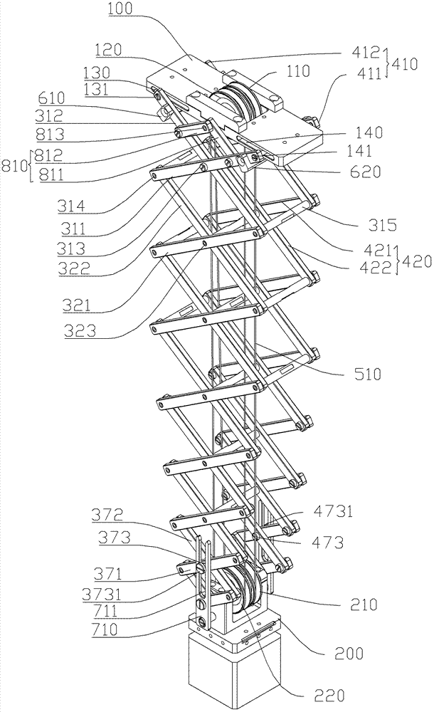
[0047] figure 1 It is a structural schematic diagram of Embodiment 1 of the present invention. figure 2 It is a schematic front view of Embodiment 1 of the present invention. image 3 It is a schematic side view of Embodiment 1 of the present invention. Such as figure 1 , figure 2 as shown, image 3 As shown, the pulley assembly includes a first pulley bracket 100 and a second pulley bracket 200 . Two rotatable fixed pulleys are arranged on the first pulley support 100 , that is, a first fixed pulley 110 and a second fixed pulley 120 . The second pulley bracket 200 is provided with two rotatable movable pulleys, that is, a first movable pulley 210 and a second movable pulley 220 . The first fixed pulley 110 and the first movable pulley 210 are a first pulley block. One end of the first flexible cable 510 is fixed on the first fixed pulley 110 , and the other end successively goes around the first movable pulley 210 , the second fixed pulley 120 and the second movable pu...

Embodiment 2

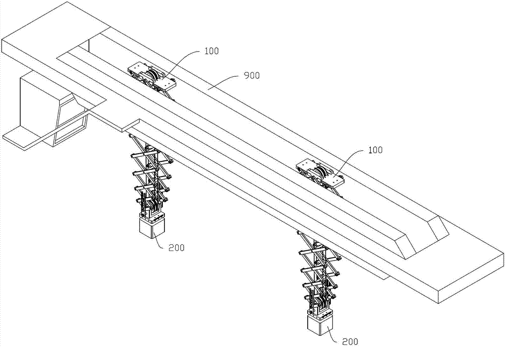
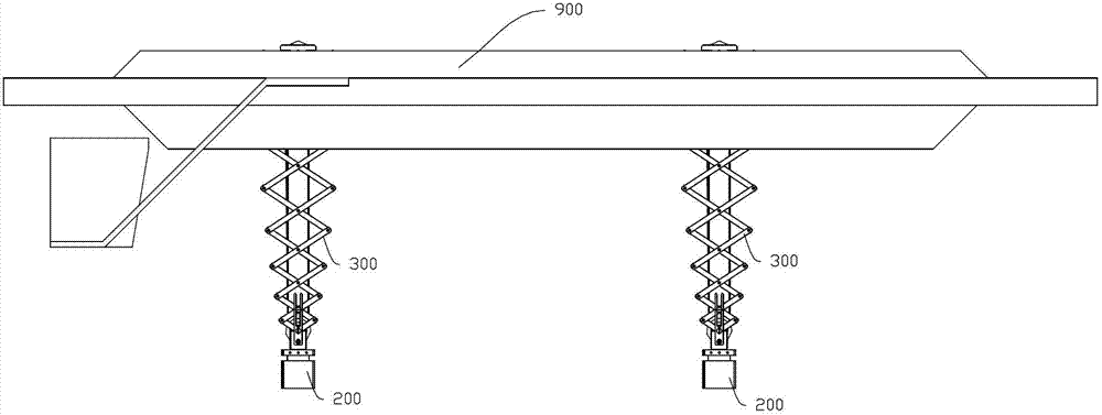
[0062] Figure 5 It is a schematic diagram of the application structure of Embodiment 2 of the present invention. Fig. 6 is a front view of Embodiment 2 of the present invention. Such as Figure 5 As shown in FIG. 6 , the gantry crane includes a beam 900 . The two first pulley brackets 100 are arranged on the beam 900 so as to be movable along the beam. A hook (not shown in the figure) is installed on the second pulley bracket 200 for hooking objects.

[0063] The usage method of the present invention is as follows: the first pulley bracket 100 first moves along the beam 900 to a required position in the horizontal direction. The winding device works to wind the first flexible cable 510, and uses the first flexible cable 510 to pull the first movable pulley 210 and the second movable pulley 220 upwards, so that the first movable pulley 210, the second movable pulley 220 and the second pulley bracket 200 can move upward and approach The first pulley bracket 100. When the ...


PUM


Abstract

The invention discloses a pulley assembly, which comprises a fixed pulley, a movable pulley and a flexible cable, wherein the fixed pulley is rotatably arranged; the movable pulley is rotatably arranged; and the flexible cable winds on the fixed pulley and the movable pulley. The pulley assembly is characterized in that the fixed pulley is rotatably arranged on a first pulley bracket and the movable pulley is rotatably arranged on a second pulley bracket. The pulley assembly also comprises a connecting piece, the length of which can be adjusted. The connecting piece is connected with the first pulley bracket and the second pulley bracket. The length of the connecting piece can be adjusted when the second pulley bracket moves towards or away from the first pulley bracket. The problem that the second pulley bracket swings when the flexible cable is only used is avoided. As the rigid connecting piece is adopted, the second pulley bracket can easily move to an expected position, and worker operation is not required, thus reducing labor intensity and avoiding danger. The flexible cable winds from two sides of a pivot, so as to prevent winding of the flexible cable from influencing the usage.

Description

technical field [0001] The invention relates to a pulley assembly and a crane. Background technique [0002] The pulley assembly bypasses the fixed pulley and the movable pulley respectively through flexible cables. Based on the requirements of use, the cables are flexible, otherwise they cannot be used. When applied on a large crane, the hook is connected with the movable pulley. The hook and movable pulley hang down by their own gravity, and the hook and movable pulley are moved to the required position by the boom of the crane. However, when the hook and the movable pulley move, it is difficult for the hook and the movable pulley to move to the required position accurately in the horizontal direction, and they swing back and forth when moving, so the hook can only be moved to the required position by manual operation of the worker. Due to the heavy weight of the hook and the movable pulley of the large-scale hoisting machinery, the height of the lifted objects is diffe...

Claims


Application Information

Patent Timeline
Patent Type & Authority Applications(China)
IPC IPC(8): B66C13/06
Inventor 孙耀兰鹏飞
Owner 上海敏坚实业有限公司
Why Eureka
Try Eureka