LED (Light-Emitting Diode) lamp with ducted convection radiating channel

A heat dissipation channel and LED lamp technology, applied in lighting and heating equipment, cooling/heating devices of lighting devices, lighting devices, etc., can solve the problems of insufficient heat dissipation, large radiator size, and power failure, etc., to achieve Enhance the ability of air convection heat dissipation, increase the heat dissipation area, and improve the effect of heat dissipation

Inactive Publication Date: 2012-11-07
浙江光锥科技有限公司
View PDF5 Cites 10 Cited by
  • Summary
  • Abstract
  • Description
  • Claims
  • Application Information

AI Technical Summary

Problems solved by technology

At present, the method of heat sink is generally used to realize heat dissipation: in outdoor lighting, there is generally no strict requirement on the volume of the lamp, and the heat sink can be made relatively large to achieve faster heat dissipation, and the power of the LED lamp can be made very large ;Compared with outdoor LED lamps, indoor LED lamps ha

Method used


Image

  • LED (Light-Emitting Diode) lamp with ducted convection radiating channel
  • LED (Light-Emitting Diode) lamp with ducted convection radiating channel
  • LED (Light-Emitting Diode) lamp with ducted convection radiating channel

Examples


Embodiment 1

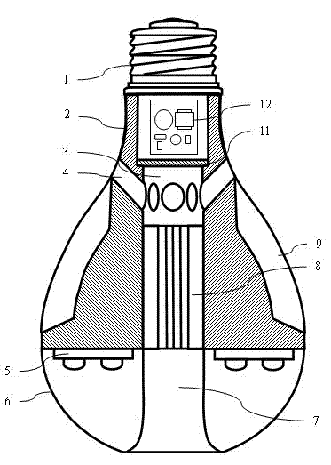
[0015] like figure 1 As shown, the present invention has an LED lamp with a ducted convective heat dissipation channel, including a lamp cap 1, a heat dissipation lamp body 2, an LED light source 5, a light distribution lampshade 6, a partition 11 and a driving circuit 12; the heat dissipation lamp body 2 is hollow and annular , the upper end is connected with the lamp cap 1; the heat dissipation lamp body 2, the lamp cap 1 and the partition 11 form a cavity, the driving circuit 12 is located in this cavity, one end is connected with the lamp cap 1, and the other end is connected with the LED light source 5; the LED light source 5 is distributed in a ring At the bottom of the heat dissipation lamp holder 2, it is covered and sealed by the light distribution lampshade 6.

[0016] The heat dissipation lamp holder 2 is made of metal, plastic, etc., and is provided with an inner hole 3 and a plurality of ventilation holes 4 connected with the inner hole 3; the ventilation holes 4 ...

Embodiment 2

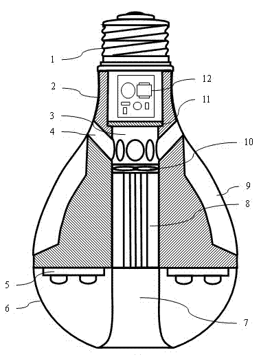
[0021] like image 3 As shown, the difference between the structure of this embodiment and that of Embodiment 1 is that a fan 10 is installed on the top of the inner cooling fin 8 of the inner hole 3 , and the fan 10 is connected to a driving circuit 12 . The fan 10 can greatly accelerate the air flow in the duct, thereby accelerating heat dissipation without increasing the volume of the LED lamp. In this embodiment, the cooperative design of the fan 10 and the duct can realize an LED lamp with small size and high power.

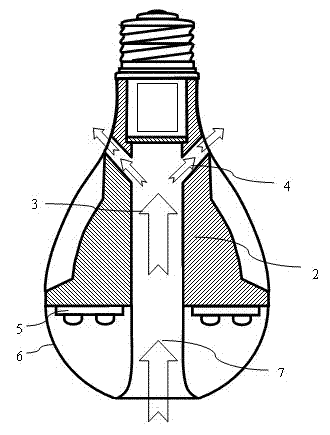
[0022] like Figure 4 As shown, the present invention arranges the outer heat dissipation fins 9 on the heat dissipation lamp body 2, and also arranges the inner heat dissipation fins 8 along the hole wall in the inner hole 3, which increases the heat dissipation area and helps the fixed fan 10 at the same time. . The light distribution lampshade 6 adopts a ring-shaped curved surface design, and uses frosted, film-coated and other uniform light design...


PUM


Abstract

The invention discloses an LED (Light-Emitting Diode) lamp with a ducted convection radiating channel. The LED lamp mainly comprises a lamp cap, a radiating lamp body, a light distribution lamp shade, an LED light source and a driving circuit, wherein an inner bore of the radiating lamp body and an outer bore of the light distribution lamp shade are communicated to form a duct, and communicated with a vent hole at the upper part of the radiating lamp body to form a convection radiating channel, an external radiating fin is arranged outside the radiating lamp body, an internal radiating fin is arranged in the inner bore, the LED light source is arranged at the bottom of the radiating lamp body circularly, the driving circuit is arranged in a cavity formed by the lamp cap and the radiating lamp body, and a partition separates the driving circuit from the duct. An external power supply is introduced in the driving circuit by the lamp cap, and the driving circuit outputs current to drive the LED light source. By utilizing a chimney formed by a duct, the radiation capacity of the LED lamp is greatly enhanced, and the service life of the LED lamp is prolonged. If an active radiating device such a fan and the like is arranged in the duct, the LED lamp with larger power can be realized.

Description

technical field [0001] The invention relates to an LED lamp, in particular to an LED lamp with a ducted convection cooling channel. Background technique [0002] In recent years, energy saving and environmental protection, and creating a low-carbon society have become the basic policies of countries all over the world. As a new generation of green lighting sources, LED light sources have shown incomparable excellent characteristics of traditional light sources in terms of energy saving and environmental protection. They are widely used in roads, squares, Indoor and other occasions. [0003] LED is used as a cold light source, about 20% of the energy will be converted into light, and the remaining 80% of the energy will be emitted in the form of heat. With the use of LED lights, the temperature will rise accordingly. In order for the LED to work normally, heat dissipation It has become a problem that must be solved. At present, the method of heat sink is generally used to r...

Claims


Application Information

Patent Timeline
IPC IPC(8): F21S2/00F21V29/00F21V29/02F21Y101/02F21V29/50F21V29/67F21V29/74
Inventor 符建陆哲谷颖杰罗晓伟董璇璇
Owner 浙江光锥科技有限公司
Why Eureka
Try Eureka