
Parallelism inspection tool for ball screw and guiding rail at gantry machining center

A machining center, ball screw technology, applied in the direction of angle/taper measurement, etc., can solve the problems of reading changes, affecting the reading accuracy, etc., to achieve the effect of convenient reading, improve measurement accuracy, and improve detection accuracy

Inactive Publication Date: 2012-11-07
南通京鼎机械科技有限公司
View PDF5 Cites 18 Cited by
  • Summary
  • Abstract
  • Description
  • Claims
  • Application Information

AI Technical Summary

Problems solved by technology

The disadvantage of this type is that although the dial indicator moves along the surface of the screw rod when it moves, its measuring head will jump when passing through the spiral groove of the screw rod, which makes the reading constantly change and affects the accuracy of the reading

Method used


Image

  • Parallelism inspection tool for ball screw and guiding rail at gantry machining center

Examples


Embodiment Construction

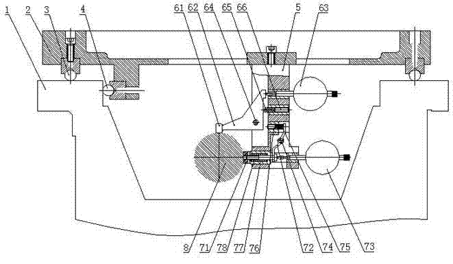
[0019] like figure 1 As shown, including guide rail 1, bridge plate 2, end limit 3, side limit 4, mounting plate 5, measuring block A61, toggle lever A62, dial indicator A63, positioning pin A64, return spring A65, measuring block B71 , Toggle lever B72, dial indicator B73, positioning pin B74 and return spring B75.

[0020] The above-mentioned bridge plate 2 is placed on the guide rail 1 , and a guide and limit assembly that can guide the bridge plate 2 along the extending direction of the guide rail 1 is arranged on it.

[0021] The guide limiter includes an end limiter 3 and a side limiter 4 installed on the lower end surface of the bridge plate 2. The end limiter 3 is against the upper end surface of the guide rail 1, and the side limiter 4 is against the inner wall of the guide rail. In this embodiment, the end limit 3 and the side limit 4 are cylindrical limit mandrels whose axes are parallel to the extending direction of the guide rail.

[0022] The middle part of the...


PUM


Abstract

The invention relates to a parallelism inspection tool for a ball screw and a guiding rail at a gantry machining center. The innovative point is that the tool includes a bridge plate arranged on the guide rail, and a mounting board fixed in the middle of the bridge plate, wherein a guiding limit component used for guiding the bridge plate in the guiding rail extending direction is arranged on the bridge plate; a screw rod-above bus measurement mechanism and a screw rod-side bus measurement mechanism both used for detecting the offset of a screw rod are mounted on the mounting board simultaneously. The tool has the advantages as follows: under the guiding of the guiding limit component, the bridge plate moves in the guiding rail extending direction, so that the screw rod-above bus measurement mechanism and the screw rod-side bus measurement mechanism can move in the guiding rail extending direction simultaneously, and dial indicators in the screw rod-above bus measurement mechanism and the screw rod-side bus measurement mechanism detect bounce amount when the measurement mechanisms pass by the surface of the screw rod, as a result, the parallelism of the screw rod and the guiding rail can be judged, and the detection is quick and convenient.

Description

technical field [0001] The invention relates to an inspection tool, in particular to an inspection tool for the parallelism between a ball screw and a guide rail of a gantry machining center. Background technique [0002] The ball screw is composed of a screw, a nut and a ball. Its function is to convert rotary motion into linear motion. It is widely used in various industrial equipment and precision instruments due to its small frictional resistance. When the ball screw is in use, it is used with the guide rail, guided by the guide rail, and driven and positioned by the ball screw. The parallelism between the guide rail and the ball screw directly affects the accuracy of positioning and the service life of the ball screw. [0003] The traditional method of detecting the parallelism between the ball screw and the guide rail uses the measuring head of the dial gauge to touch the surface of the screw, and the parallelism is confirmed by moving the dial gauge along the directi...

Claims


Application Information

Patent Timeline
Patent Type & Authority Applications(China)
IPC IPC(8): G01B5/24
Inventor 邵锋冒晓波杨雷姚杨
Owner 南通京鼎机械科技有限公司
Learn More