
Low-pressure carbon dioxide intelligent fire-fighting vehicle

A carbon dioxide, fire truck technology, applied in fire rescue and other directions, can solve problems such as weak impact force, inability to carry out fire fighting, inability to break windows or exterior walls, etc., to ensure normal operation.

Active Publication Date: 2012-11-14
南理创通(天津)智能科技有限公司
View PDF3 Cites 11 Cited by
  • Summary
  • Abstract
  • Description
  • Claims
  • Application Information

AI Technical Summary

Problems solved by technology

[0002] Existing fire trucks can extinguish fires in high-rise buildings, but they can only use water as a fire extinguishing agent; low-pressure carbon dioxide fire extinguishing has the advantages of environmental protection, safety, and economy, and can provide non-polluting and clean fire extinguishing for fires caused by water-avoiding substances. However, it is mainly used for indoor fixed automatic fire extinguishing. For high-rise buildings and their indoor mobile fire extinguishing, this method is not suitable, because the impact force of existing gas jet fire extinguishing is weak, and it is impossible to break windows or outer walls. There is also no device that can effectively transport gaseous fire extinguishing agents such as carbon dioxide to high-rise buildings and simultaneously destroy the outer walls or doors and windows of buildings, so that effective fire extinguishing cannot be implemented.

Method used


Image

  • Low-pressure carbon dioxide intelligent fire-fighting vehicle
  • Low-pressure carbon dioxide intelligent fire-fighting vehicle
  • Low-pressure carbon dioxide intelligent fire-fighting vehicle

Examples


Embodiment Construction

[0019] The present invention will be described in further detail below in conjunction with the accompanying drawings.

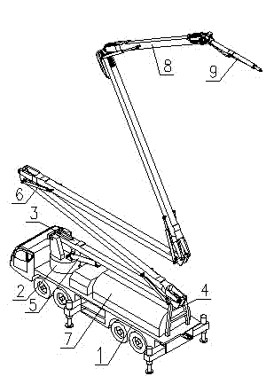
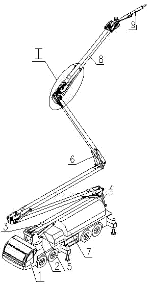
[0020] Such as Figure 1 to Figure 7 As shown, the low-pressure carbon dioxide intelligent fire truck of this embodiment includes a vehicle 1 provided with a rotary table 2 and a fuel tank (not shown), the rotary table 2 is provided with a five-stage luffing arm, and the bottom variable One end of the luffing arm 3 is hinged on the rotary table 2 through a hinge shaft, and a support frame 4 is provided on the vehicle 1 on the opposite side of the rotary table. The hinged end of the luffing arm 3 and the rotary table 2 is connected by a double-acting oil cylinder 5, and the hinged ends of two adjacent luffing arms are connected by two symmetrically arranged double-acting oil cylinders 6, and each luffing arm is equipped with a hollow inner There is an oil inlet pipe and an oil return pipe fixed in the inner cavity of each luffing arm, and the two oil pipes co...


PUM


Abstract

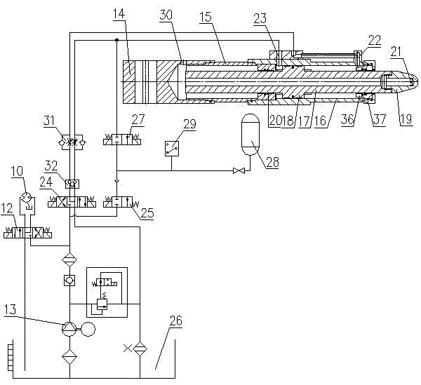
The invention discloses a low-pressure carbon dioxide intelligent fire-fighting vehicle, which comprises a vehicle provided with a rotary table, a storage tank, a refrigerating machine and an oil tank. The rotary table is provided with multiple stages of variable-amplitude arms; the front end of the top variable-amplitude arm is provided with a working arm assembly; the working arm assembly comprises a hydraulic motor, a key shaft, a hinged support, an air cylinder and a cylinder barrel; a hollow piston rod is arranged in the air cylinder and the cylinder barrel; the front end of the piston rod is fixedly connected with an impact head; a blind hole is arranged in the impact head; the front end of the impact head is provided with a plurality of jet holes; the front port and the rear port of the cylinder barrel are respectively and mutually connected with a reversing valve; the oil inlet of the reversing valve is mutually connected with an oil pump and the oil inlet of a bypass reversing valve; the working port of the bypass reversing valve is also mutually connected with a rear port on the cylinder barrel through a valve; and the connected oil line of the bypass reversing valve and the valve is provided with an energy accumulator. According to the low-pressure carbon dioxide intelligent fire-fighting vehicle disclosed by the invention, a gas extinguishing agent can be effectively conveyed to a high-rise, and meanwhile, the outer walls or doors and windows of a building are broken, thus, effective extinguishment can be implemented on the high-rise building or the interior of the high-rise building, and the long-term operation of equipment is ensured.

Description

technical field [0001] The invention relates to a low-pressure carbon dioxide fire engine. Background technique [0002] Existing fire trucks can extinguish fires in high-rise buildings, but they can only use water as a fire extinguishing agent; low-pressure carbon dioxide fire extinguishing has the advantages of environmental protection, safety, and economy, and can provide non-polluting and clean fire extinguishing for fires caused by water-avoiding substances. However, it is mainly used for indoor fixed automatic fire extinguishing. For high-rise buildings and their indoor mobile fire extinguishing, this method is not suitable, because the impact force of existing gas jet fire extinguishing is weak, and it is impossible to break windows or outer walls. Also there is no device that can effectively deliver gaseous fire extinguishing agents such as carbon dioxide to high-rises and simultaneously destroy the outer walls or doors and windows of buildings, thereby effectivel...

Claims


Application Information

Patent Timeline
IPC IPC(8): A62C27/00
Inventor 金晓辉陈斌王利
Owner 南理创通(天津)智能科技有限公司
Learn More