Modified double-layered steel plate concrete shear wall and construction method thereof

A steel plate concrete and construction method technology, applied in walls, building components, buildings, etc., can solve problems such as elastic-plastic local buckling, improve the ability to resist buckling deformation, save welding work, and improve overall restraint and shear resistance Effect

Inactive Publication Date: 2012-11-14
SOUTH CHINA UNIV OF TECH
View PDF6 Cites 5 Cited by
  • Summary
  • Abstract
  • Description
  • Claims
  • Application Information

AI Technical Summary

Problems solved by technology

[0005] However, the above technical solution still has the following disadvantages: the area between the restraint rods is still prone to elastic-plastic local buckling phenomenon, and once buckling deformation occurs locally, the buckling deformation will bypass the strong restraint area of ​​the restraint rods and pass through the gap between the restraint rods. Gap spread and spread

Method used


Image

  • Modified double-layered steel plate concrete shear wall and construction method thereof
  • Modified double-layered steel plate concrete shear wall and construction method thereof
  • Modified double-layered steel plate concrete shear wall and construction method thereof

Examples


Embodiment 1

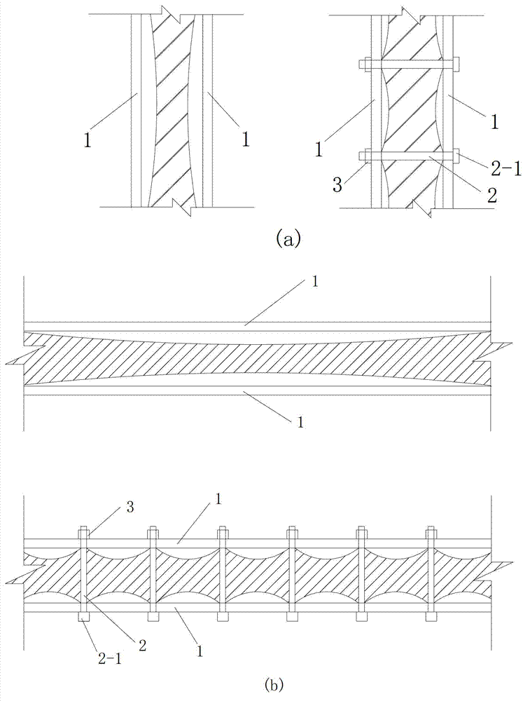
[0043] see Figure 4 and Figure 5 The improved double-layer steel plate concrete shear wall of this embodiment is set in the rectangular space surrounded by the beam 6 (including the upper beam and the lower beam) and the frame column 7 (including the left frame column and the right frame column). The force wall is composed of two opposite rectangular steel plates 1 , a concrete wall 4 filled between the two steel plates 1 , restraining rods 2 connected to the two steel plates 1 , stiffening strips 5 and nuts 3 .

[0044] The restraint rods 2 are arranged longitudinally and transversely to form a matrix of 6 rows×6 columns, and the steel plate 1 is provided with holes through which the restraint rods 2 are installed corresponding to the installation positions of the restraint rods 2 .

[0045] The stiffening strip 5 is a strip-shaped steel plate with a rectangular cross section, which can be cut from corner materials; The strips 5a are arranged on the outside of the steel p...

Embodiment 2

[0049] see Figure 7 In this embodiment, on the basis of Example 1, transverse stiffening bands 5b are also arranged on the outside of the steel plate 1 (i.e., arranged in the horizontal direction). Correspondingly, the connection mode of the transverse stiffening strip 5 b to the steel plate 1 and the restraint tie rod 2 is the same as the connection manner of the longitudinal stiffening strip 5 a to the steel plate 1 and the restraint tie rod 2 . The intersecting parts of the longitudinal stiffening strips 5a and the transverse stiffening strips 5b are integrated, which can be formed by welding or integrally formed.

[0050] Embodiments other than the above in this embodiment are the same as in Embodiment 1.

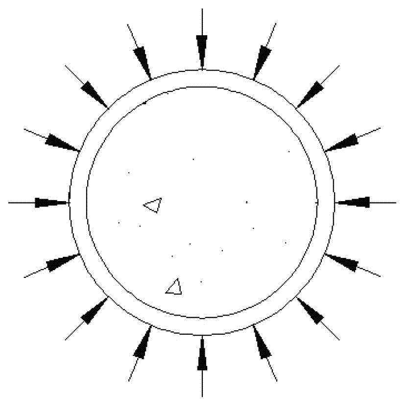
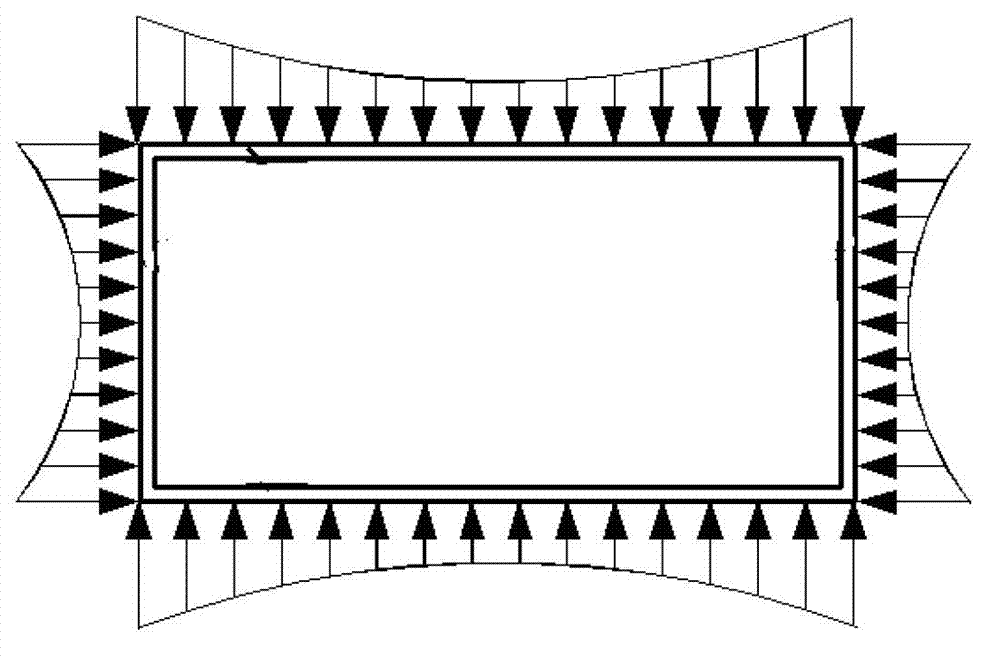
[0051] see Figure 8 , the figure shows the difference between the core concrete constrained area of ​​the double-layer steel plate concrete shear wall with the restraint tie rod 2 and the improved double-layer steel plate concrete shear wall of the present embodimen...

Embodiment 3

[0053] see Figure 9 The difference between this embodiment and Embodiment 1 is that in this embodiment, the stiffening strip is a transverse stiffening strip 5b, which is arranged on the inner side of the steel plate 1, and the transverse stiffening strip 5b and There is no need for welding between the steel plates 1, and only the bolt connection structure in Embodiment 1 can be used.

[0054] This embodiment can save the welding process, shorten the construction period, and increase the construction speed. At the same time, setting the stiffening belt on the inner side of the steel plate 1 can prevent the stiffening belt from being exposed to the air, thereby saving the work of taking anti-oxidation measures for the stiffening belt. .

[0055] Embodiments other than the above in this embodiment are the same as in Embodiment 1.


PUM


Abstract

The invention discloses a modified double-layered steel plate concrete shear wall and a construction method thereof. The modified double-layered steel plate concrete shear wall comprises two layers of steel plates and a concrete wall body disposed between the two layers of steel plates. Binding bars are connected between the two layers of steel plates. Reinforcing bars are disposed on each steel plate. Two ends of each binding bar penetrate through the reinforcing bars and the steel plates. The binding bars, the reinforcing bars and the steel plates are connected with one another. By disposing the binding bars and the reinforcing bars, binding capability of the steel plates to core concrete is improved and buckling and developing of areas among the binding bars are delayed and blocked. When the binding bars are threaded and the reinforcing bars are connected with the steel plates through spot-welding connection, bolt connection or a combination of spot-welding connection and bolt connection, influences of welding residual stress can be relieved, construction is simple and easy, thickness of the steel plates can be reduced evidently, welding processes can be omitted or reduced greatly, and construction cost can be lowered.

Description

technical field [0001] The invention relates to building structures, in particular to an improved double-layer steel plate concrete shear wall and a construction method thereof. Background technique [0002] Steel tube concrete structure, steel plate concrete shear wall and other structures effectively combine the advantages of steel and concrete, and have the advantages of high bearing capacity, good plasticity, superior earthquake resistance and fire resistance, material saving and simple construction. The application of steel tube concrete columns and steel plate concrete shear walls in high-rise buildings, especially super high-rise buildings, has obvious advantages. [0003] The circular steel pipe concrete column provides uniform pressure on the inner filling concrete along the circumferential direction (see figure 1 ), while the confinement effect of the steel plate on the inner concrete of the rectangular steel tube concrete column (double-layer steel plate concrete...

Claims


Application Information

Patent Timeline
Patent Type & Authority Applications(China)
IPC IPC(8): E04B2/86E04G21/00
Inventor 蔡健郑新志陈庆军杨春左志亮姜正荣
Owner SOUTH CHINA UNIV OF TECH
Why Eureka
Try Eureka