Valve device and high pressure pump using the same

A technology of valve device and valve seat, which is applied in the direction of valve device, valve operation/release device, parts of pumping device for elastic fluid, etc., can solve the problem that it is difficult to fully suppress the automatic closing of valve components, and achieve Miniaturization and the effect of reducing the maximum output

Active Publication Date: 2012-11-14
DENSO CORP
View PDF10 Cites 4 Cited by
  • Summary
  • Abstract
  • Description
  • Claims
  • Application Information

AI Technical Summary

Problems solved by technology

Therefore, it is difficult to sufficiently sup

Method used


Image

  • Valve device and high pressure pump using the same
  • Valve device and high pressure pump using the same
  • Valve device and high pressure pump using the same

Examples


no. 1 example

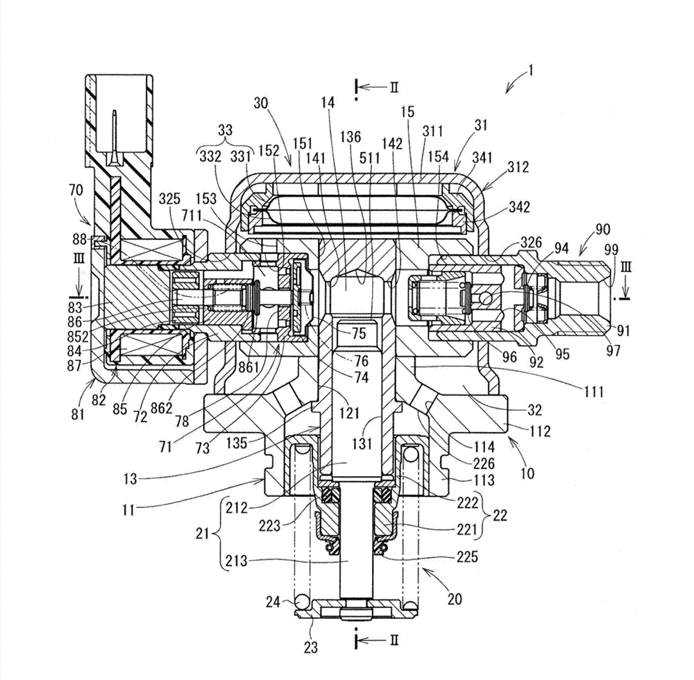
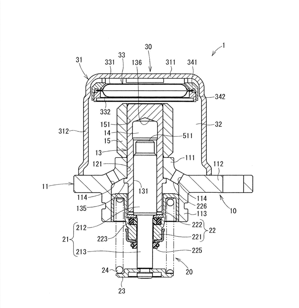
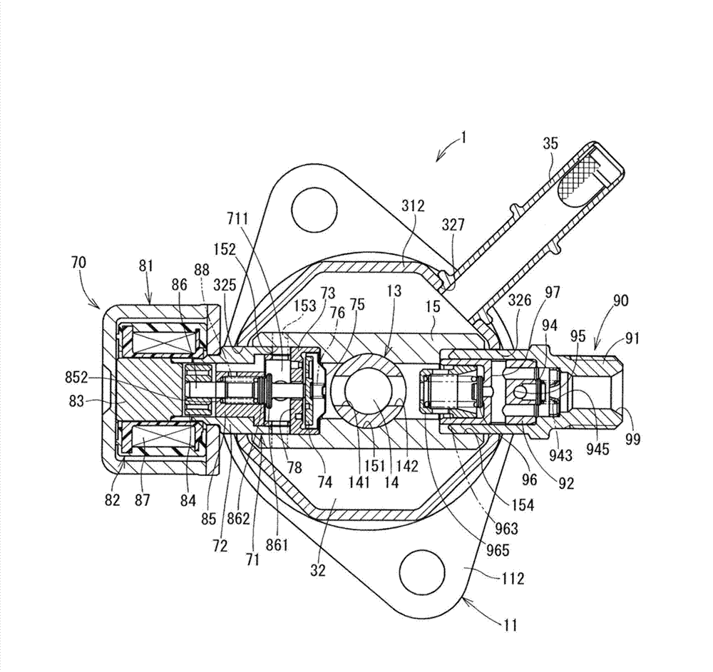
[0082] The high pressure pump of the first embodiment of the present invention is shown in Figures 1 to 3 middle. The high-pressure pump 1 is a fuel pump that compresses fuel supplied from a fuel tank not shown and discharges the pressurized fuel into a fuel rail. The high-pressure pump 1 is provided with a main body portion 10 , a fuel supply portion 30 , a plunger portion 20 , a fuel suction portion 70 and a fuel discharge release portion 90 . The fuel intake portion 70 corresponds to "valve device" in the following description, figure 1 The upper side of will be taken as "on", "up" or "above", and figure 1 The lower side of will be read as "below", "down" or "under".

[0083] The main body portion 10 includes a lower case 11 , a cylinder 13 and an upper case 15 . The lower housing 11 has a cylindrical cylinder holding portion 111 , an annular flange portion 112 protruding radially outward from a lower portion of the cylinder holding portion 111 , and a cylindrical engi...

no. 2 example

[0135] The following will refer to Figure 9 The suction valve portion of the second embodiment will be described. The first pressure equalization groove 421 and the second pressure equalization groove 422 of the suction valve portion 41 are formed to the suction valve member 42 . Therefore, since the weight of the suction valve member 42 becomes lighter, the attractive force of the electromagnetic drive unit can become smaller. Therefore, miniaturization of the electromagnetic drive unit is achieved. The processing cost of the second suction valve main body 43 can be reduced.

no. 3 example

[0137] The following will refer to Figure 10 The suction valve portion of the third embodiment of the present invention will be described. The radially inner wall of the first convex portion 451 of the suction valve member 45 of the suction valve portion 44 is closer to the first passage 743 toward the valve seat 78 . Therefore, fuel from the pressure chamber toward the first convex portion 451 is introduced radially inward along the radially inner wall of the first convex portion 451 . Therefore, at the time of metering, the fuel from the pressure chamber toward the suction valve member 45 can be smoothly guided to the first passage 743 .


PUM


Abstract

The present invention provides a valve device and a high pressure pump using the same. A valve seat (78) has an inner passage (781) and outer passages (782). A suction valve member (74) has first passages (743) and a first projection portion (744) that guides, to the first passages (743), the fuel that flows from a pressure chamber at the time of valve opening. Therefore, an action force by the dynamic pressure applied to the suction valve member (74) in the valve closing direction is reduced. An action force by the pressure of fuel that flows into pressure equalization grooves (746, 784, 785) counterbalances the action force by the dynamic pressure of the suction valve member (74). Therefore, self-closing by the dynamic pressure can be inhibited, and the maximum output of an electromagnetic driving unit can be reduced. Fuel flows through a passage radially outside the suction valve member (74) and the first passages (743). A fluid passage area is securable even when a lift amount of the suction valve member (74) is small. The maximum output of an electromagnetic drive unit also can be reduced.

Description

technical field [0001] The present invention relates to a valve device capable of opening and closing a channel and a high-pressure pump using the valve device. Background technique [0002] Valve means are used to block passages in which fluid flows. Such a valve arrangement includes a valve member that moves towards and away from a valve seat within the valve body. In this type of valve arrangement, the valve member is pressed against the valve seat for valve closure and the valve member is separated from the valve seat for valve opening. The position of the valve member is controlled by the movable member of the drive unit. For example, the valve member is electromagnetically actuated. [0003] The valve device includes a normally open type valve in which the valve is opened when the drive unit is not in operation and a normally closed type valve in which the valve is closed when the drive unit is not in operation. In the normally open type, the valve member is biased...

Claims


Application Information

Patent Timeline
IPC IPC(8): F02M59/46
CPCF02M59/368F02M59/462F02M63/0078F02M63/0035F02M63/0075F02M63/0077F02M59/46F02M59/466F16K31/06F04B53/14F04B7/0076F04B53/103F04B53/16F04B53/1032F16K31/44F04B53/1087F16K1/42F02M59/02F04B19/22F16K1/32F16K1/50F16K1/54F16K31/0655
Inventor 黑柳正利井上宏史越本振一郎
Owner DENSO CORP
Why Eureka
Try Eureka