LED project lamp using lamp shell support as mounting interface support structure

A technology for LED floodlights and installation interfaces, which is applied to components of lighting devices, cooling/heating devices of lighting devices, light sources, etc., and can solve the problems of high manufacturing cost, non-common use, and small batches of LED lighting products , to achieve the effect of facilitating standardized large-scale production, high versatility and interchangeability, low cost and practical effect

Active Publication Date: 2014-06-11
GUIZHOU GUANGPUSEN PHOTOELECTRIC
View PDF6 Cites 0 Cited by
  • Summary
  • Abstract
  • Description
  • Claims
  • Application Information

AI Technical Summary

Problems solved by technology

This has brought a series of fatal problems such as high manufacturing cost, inconvenient use, and difficult maintenance to LED lighting products.
First of all, it is impossible to achieve national and even global unified standardized production in manufacturing, resulting in many product specifications, few batches, and high prices; secondly, the products of each company are various, not universal, let alone interchangeable; thirdly, product failure Sometimes it is necessary to remove the LED optical module, driving power supply, lamps and other assemblies as a whole for maintenance, which is extremely inconvenient to maintain, and it is very easy to cause defects such as expansion of faults, delay in maintenance, and high maintenance costs.
These defects have greatly restricted the promotion and use of LED lighting, and are flaws in the promotion of LED lighting products.

Method used


Image

  • LED project lamp using lamp shell support as mounting interface support structure
  • LED project lamp using lamp shell support as mounting interface support structure
  • LED project lamp using lamp shell support as mounting interface support structure

Examples


Embodiment

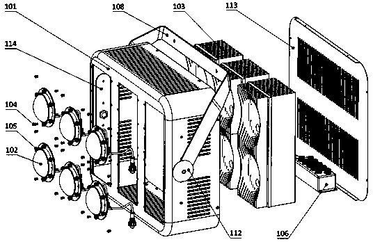
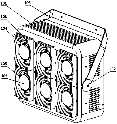
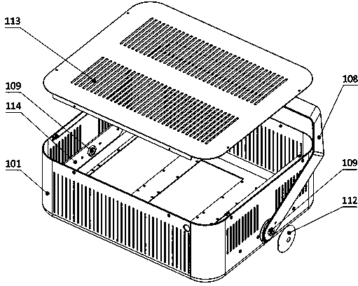
[0060] An LED flood light using a lamp housing bracket as an installation interface bracket structure, such as figure 1 , figure 2 and image 3 As shown, it includes a lamp housing bracket 101 and an LED bulb 102. The lamp housing bracket 101 is a rectangular box with an opening on one side. The lamp housing bracket 101 is provided with an extruded double-sided radiator 103. The lamp housing bracket 101 is opposite to the opening. There are openings on the surface for installing the extruded double-sided radiator 103. The lamp housing bracket 101 is provided with ventilation holes on the other surfaces except the opening and the side with the opening. The lamp housing bracket 101 is arranged on the two sides. The fixing components on the side are installed and fixed; the extruded double-sided heat sink 103 is provided with an installation interface for installing the LED bulb 102 . The fixing assembly includes a lamp fixing bracket 108 and a reinforcing plate 114, the reinf...


PUM


Abstract

The invention discloses an LED project lamp using a lamp shell support as a mounting interface support structure. The LED project lamp comprises the lamp shell support (101) and LED bulbs (102), the lamp shell support (101) is a rectangular box with an opening on one surface, the surface opposite to the opening of the lamp shell support (101) is provided with a hole for mounting an extruded double-sided radiator (103), vent holes are arranged on the other surfaces of the lamp shell support (101) except for the surface with the opening and the surface with the hole, the lamp shell support (101) is fixedly mounted by fixing components arranged on two sides of the lamp shell support, and mounting surfaces for mounting the LED bulbs (102) are arranged on the extruded double-sided radiator (103). The LED project lamp is simple in structure, low in manufacturing cost and convenient to mount, use and maintain. The bulbs of the LED project lamp, a lighting fixture and a lighting control product can be respectively independent in production and use, production links of LED lighting products are greatly decreased, batch production is improved, and standard large-scale production and industrialization of the energy-saving LED lighting products are facilitated.

Description

technical field [0001] The invention relates to an LED floodlight, in particular to an LED floodlight using a lamp housing bracket as an installation interface bracket structure. Background technique [0002] As a new generation of lighting technology, LED semiconductor lighting has the advantages of high photoelectric conversion rate, easy control of light source direction, easy control of lighting period and method, high color rendering of light source, and high power factor under reasonable design. The five major energy-saving advantages are favored by global investors and vigorously supported by governments around the world. Most of the current luminous efficiency of LED lighting can exceed 70LM / W, which is more energy-saving than traditional energy-saving lamps. Theoretically, the luminous efficiency of green LED can be as high as 683LM / W; the theoretical efficiency of white LED can also reach 182.45LM / W, so there is huge room for LED lighting efficiency improvement. ...

Claims


Application Information

Patent Timeline
Patent Type & Authority Patents(China)
IPC IPC(8): F21S8/00F21V19/00F21V29/00F21V31/00F21V23/06F21V17/00F21V17/10F21Y101/02F21V29/76F21V29/83
Inventor 张继强张哲源
Owner GUIZHOU GUANGPUSEN PHOTOELECTRIC
Why Eureka
Try Eureka