Novel auxiliary winding of transformer

A technology of auxiliary winding and transformer, applied in the direction of transformer/inductor coil/winding/connection, etc., can solve the problems of unbalanced ampere-turn of main winding, occupying space of main winding, affecting the layout of main winding, etc. Outgoing line and insulation distance, the effect of enhancing the ability to resist short circuit

Active Publication Date: 2015-04-22
NEWONDER SPECIAL ELECTRIC
View PDF4 Cites 0 Cited by
  • Summary
  • Abstract
  • Description
  • Claims
  • Application Information

AI Technical Summary

Problems solved by technology

[0004] The purpose of the present invention is to solve the problem in the prior art that the auxiliary winding of the transformer needs to occupy the space of the main winding, which affects the layout of the main winding and thus leads to the imbalance of the ampere-turn of the main winding and increases the cost of the transformer.

Method used


Image

  • Novel auxiliary winding of transformer
  • Novel auxiliary winding of transformer
  • Novel auxiliary winding of transformer

Examples


Embodiment 1

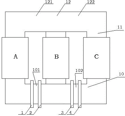
[0016] Embodiment one, see figure 1 , 2 , the transformer of the present invention is shown in the figure, see figure 1 , A, B, and C in the figure are the three-phase main windings of the transformer, and the three-phase main windings A, B, and C are respectively arranged on the iron core column 11, and the upper and lower ends of the iron core column 11 are the iron yoke 12 and the iron yoke 10 , the transformer of the present invention also contains an auxiliary winding. The inventive point of the present invention is that: the auxiliary winding is arranged on the iron yoke, in this embodiment, it is arranged on the iron yoke 10, and the auxiliary winding includes four single-phase auxiliary windings 1, 2, 3, 4, Its turns ratio is: 1:1:1:1, and it is divided into two groups: single-phase winding 1, 2 and single-phase winding 3, 4. The iron core column 11 located in the middle divides the iron yoke 10 into a left iron yoke 101 and a right iron yoke 102, and there are two ...

Embodiment 2

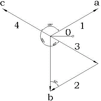
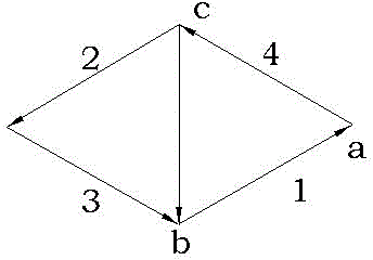
[0018] Embodiment two, see image 3 , and the difference from the previous embodiment is that another wiring method of the auxiliary winding is shown in the figure, that is, a delta connection method is used: the three-phase windings a, b, and c are connected end to end to form a closed form, and the b phase is also It is formed by the single-phase auxiliary windings 2 and 3 connected in series and reversed.

Embodiment 3

[0019] Embodiment three, see Figure 4 , 5 , another embodiment is shown in the figure, the difference from the first embodiment is that the auxiliary winding in the present invention is composed of 8 coils 1, 2, 3, 4, 5, 6, 7, 8, That is, the four single-phase auxiliary windings in the present invention are all composed of two coils (1, 2), (3, 4), (5, 6), (7, 8). The 8 coils in this embodiment are equally divided into two groups (1, 2, 3, 4), (5, 6, 7, 8) and are arranged on the left iron yokes 101, 121 and the right iron yokes 102, 122 respectively. ,Such as Figure 5 As shown: the two coils 1 and 2 on the left iron yoke 121 are connected in series to form phase a, the two coils 7 and 8 on the right iron yoke 122 are connected in series to form phase c, and the coils in the remaining two groups 3 and coil 4 are set on the left iron yoke 101 and connected in series first, coils 5 and 6 are located on the right iron yoke 102 and connected in series first, and then the two ...


PUM


Abstract

The invention relates to a novel auxiliary winding of a transformer and the transformer with the novel auxiliary winding. The novel auxiliary winding is characterized by comprising four single-phase windings which are divided into two groups, wherein the two groups are respectively arranged on two sections of iron yokes between three-phase main windings; one single-phase winding in each group serves as a and c phases of the three-phase main windings respectively; after being connected in series, the other two single-phase windings are reversed and serve as b phase; and the a, b and c three-phase main windings are connected into y shape. The auxiliary winding is simple in structure and ingenious and reasonable in wiring, so that the size of a three-phase transformer product is reduced, and the manufacturing material of the transformer is saved.

Description

technical field [0001] The invention relates to an auxiliary winding of a transformer and a transformer with the auxiliary winding. Background technique [0002] The auxiliary winding of the existing three-phase transformer is generally placed on the core column of the iron core, which can constitute a three-phase auxiliary winding. But its disadvantage is that it occupies the space of the main winding, which increases the height of the iron core of the three-phase transformer, especially for large transformers, the increase of the height of the iron core will undoubtedly increase the cost of the transformer. [0003] The utility model patent No. 200820134295 discloses a polysilicon converter transformer, which includes a primary winding, a secondary winding and an iron core. The primary winding is connected in a delta, and the secondary winding is three mutually insulated windings. The secondary winding includes an auxiliary winding for providing control power. Among them...

Claims


Application Information

Patent Timeline
Patent Type & Authority Patents(China)
IPC IPC(8): H01F27/28H01F27/30
Inventor 谭勇邓旭峰李鹏
Owner NEWONDER SPECIAL ELECTRIC
Why Eureka
Try Eureka