Unlock instant, AI-driven research and patent intelligence for your innovation.

Pulse-width modulation (PWM) switching power supply, frequency jitter circuit thereof and frequency jitter method

A switching power supply, switching frequency technology, applied in electrical components, adjusting electrical variables, output power conversion devices, etc., can solve the problem that the range of frequency jitter is not easy to control, the charging voltage of charge pump is not easy to control, and the step width cannot be controlled, etc. question

Active Publication Date: 2012-11-14
BCD (SHANGHAI) MICRO ELECTRONICS LTD
View PDF2 Cites 8 Cited by
  • Summary
  • Abstract
  • Description
  • Claims
  • Application Information

AI Technical Summary

Problems solved by technology

However, the charging voltage of the charge pump is not easy to control, ie image 3 The step width of the stepped dotted line shown in can not be controlled, which makes it difficult to control the range of frequency jitter based on the above mechanism, resulting in poor electromagnetic compatibility of the switching power supply
[0008] Through the above analysis, it can be seen that the existing technology can only realize the switching frequency jitter of the PFM switching power supply at some load points, and its frequency jitter is not easy to control, and the electromagnetic compatibility of the switching power supply is poor.

Method used


Image

  • Pulse-width modulation (PWM) switching power supply, frequency jitter circuit thereof and frequency jitter method
  • Pulse-width modulation (PWM) switching power supply, frequency jitter circuit thereof and frequency jitter method
  • Pulse-width modulation (PWM) switching power supply, frequency jitter circuit thereof and frequency jitter method

Examples


Embodiment 1

[0056] Based on the foregoing idea, the embodiment of the present invention provides a frequency jittering circuit of a PFM switching power supply, and the frequency jittering circuit includes:

[0057] The frequency jitter module is connected to the primary peak current detection comparator of the switching power supply and is used to change the reference voltage of the primary peak current detection comparator to change the primary peak current detection comparison The peak current of the primary side of the converter makes the switching frequency of the switching power supply jitter.

[0058] Wherein, the frequency jitter module includes:

[0059] A reference voltage providing unit connected to the primary peak current detection comparator;

[0060] The reference voltage controller is used to change the output voltage of the reference voltage supply unit, thereby changing the reference voltage of the primary peak current detection comparator to change the primary peak current detec...

Embodiment 2

[0120] On the basis of the above-mentioned embodiment, this embodiment provides a method for frequency jittering of PFM switching power supply to realize that the switching frequency of the switching power supply generates controllable periodic jitter at all load points, so that the The switching power supply has good electromagnetic compatibility.

[0121] The frequency jitter method changes the reference voltage of the switching power supply, thereby changing the primary-side conduction time and the secondary-side conduction time of the switching power supply, thereby causing the switching frequency of the switching power supply to jitter.

[0122] A plurality of controlled voltage sources can be used to provide a periodically changing reference voltage for the primary peak current detection comparator.

[0123] Same as the method in the first embodiment, two power sources can be used. The first voltage source and the second power source provide the reference voltage for the primar...

Embodiment 3

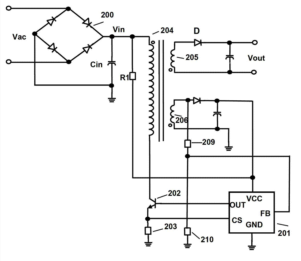
[0127] On the basis of the foregoing embodiment, this embodiment provides a PFM switching power supply. The PFM switching power supply includes a transformer with a primary winding for coupling an input power source and a secondary winding for providing the output voltage of the switching power supply. Side winding, and an auxiliary winding; a switch tube, the switch tube is a power transistor, and is coupled to the primary winding; in the first embodiment, the PFM controller is connected to the switch tube and controls the switch tube On and off.

[0128] In addition to the PFM controller, other components and the connection between the other components are figure 1 The switching power supplies shown in are the same. For the circuit structure and working principle of the switching power supply, refer to the corresponding description in the first embodiment, which will not be repeated here.

[0129] The switching power supply in this embodiment has the PFM controller described in ...


PUM


Abstract

The invention discloses a pulse-width modulation (PWM) switching power supply, a frequency jitter circuit thereof and a frequency jitter method, wherein the frequency jitter circuit comprises a frequency jitter module, wherein the frequency jitter module is connected with a primary side peak current detection comparator of the switching power supply for improving the reference voltage of the primary side peak current detection comparator, so the primary side peak current of the primary side peak current detection comparator is changed, and the switching frequency of the switching power supply is jittered. Through changing the reference voltage of the primary side peak current detection comparator to change the primary side peak current, the switching frequency of the switching power supply is jittered. The variation range of the primary side peak current is controlled through setting the variation range of the reference voltage, so the frequency jitter range of the switching power supply can be controlled, the switching frequency of the switching power supply which adopts the frequency jitter circuit can be controlled to periodically jitter, and accordingly, the switching power supply has better electromagnetic compatibility.

Description

Technical field [0001] The invention relates to the technical field of integrated circuit manufacturing technology, and more specifically, to a PFM switching power supply and a frequency jitter circuit and a frequency jitter method thereof. Background technique [0002] Switching power supply is a circuit device that uses modern power electronic technology to control the time ratio of switching on and off to maintain a stable output. Among them, a common switching power supply is a pulse frequency modulation (PFM) switching power supply with a constant current and constant voltage working mode, that is, the switching power supply controls the on and off of the switching tube through PFM to maintain a stable output, so that the entire The switching power supply system works in constant voltage or constant current mode. PFM switching power supply has a high rate of voltage change and current change, and its transformer has parasitic capacitance and parasitic inductance, which form...

Claims


Application Information

Patent Timeline
Patent Type & Authority Applications(China)
IPC IPC(8): H02M1/44H02M3/335
Inventor 张骅费瑞霞
Owner BCD (SHANGHAI) MICRO ELECTRONICS LTD
Features
  • R&D
  • Intellectual Property
  • Life Sciences
  • Materials
  • Tech Scout
  • Unparalleled Data Quality
  • Higher Quality Content
  • 60% Fewer Hallucinations
Learn More