
Power distribution method, base station, user equipment and system

A power and base station technology, applied in the field of power allocation, can solve the problems of large CQI fluctuation, affecting UE throughput, affecting UE scheduling results, etc., and achieves good resource allocation effect, throughput, and stable reception performance.

Active Publication Date: 2012-11-14
HUAWEI TECH CO LTD
View PDF3 Cites 5 Cited by
  • Summary
  • Abstract
  • Description
  • Claims
  • Application Information

AI Technical Summary

Problems solved by technology

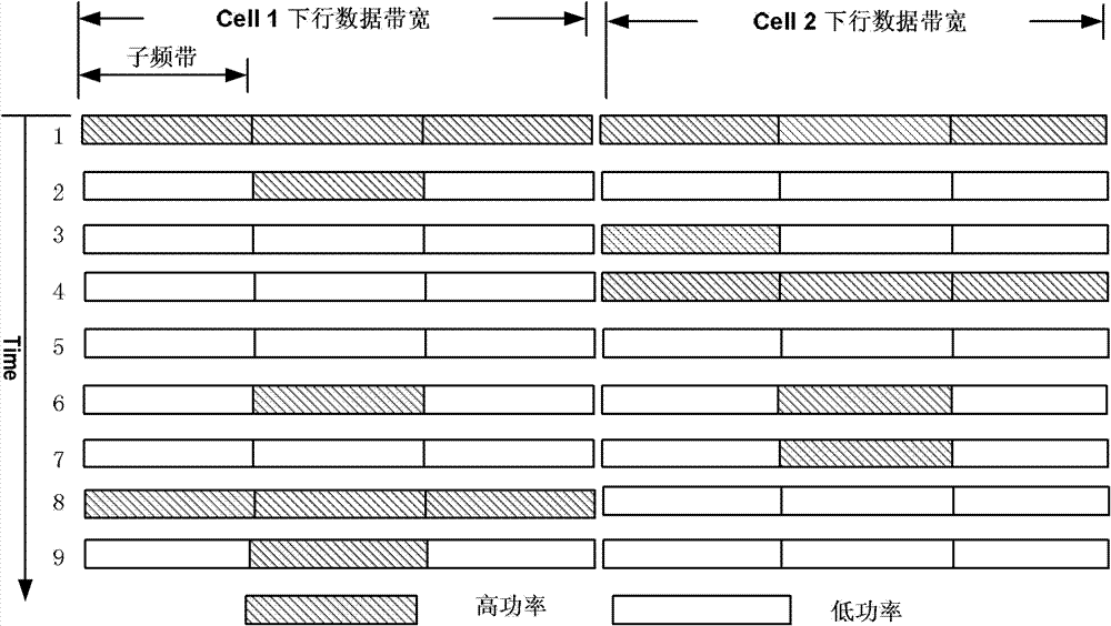
[0006] like figure 1 In the situation shown, at the first moment UE H 1 Received high-power interference from the neighboring cell cell2, at the 8th moment UE H 1 Under the low power interference of the neighboring cell cell2, at these two moments UE H 1 Both will measure the CQI at the current moment and return it to the network side, however, the UE H 1 There is a certain delay in returning the CQI to the network side. The network side cannot know the CQI at the 8th moment in time at the 8th moment, so the UE at the 1st moment will still be used at this moment. H 1 The CQI of the resource is scheduled, but in fact, due to the drastic change in the downlink transmission power of the adjacent cell cell2 at the 8th moment relative to the 1st moment, the CQI at the 1st moment is different from the CQI at the 8th moment. Great changes have taken place, and the network side cannot provide timely support for the UE H 1 Select the optimal modulation and coding method and resource allocation scheme according to the actual CQI, thus affecting the throughput of the UE
[0007] Therefore, using the existing downlink transmission power allocation method may cause large fluctuations in the CQI results measured by the UE due to drastic changes in the downlink transmission power of adjacent cells, and the network side cannot obtain real-time CQI due to delays. , when the CQI fluctuates greatly, it will affect the scheduling result of the UE on the network side, and cannot produce better resource allocation effect and throughput

Method used


Image

  • Power distribution method, base station, user equipment and system
  • Power distribution method, base station, user equipment and system
  • Power distribution method, base station, user equipment and system

Examples


Embodiment Construction

[0044] In order to make the object, technical solution and advantages of the present invention clearer, the implementation manner of the present invention will be further described in detail below in conjunction with the accompanying drawings.

[0045] In this embodiment, a method for power allocation is provided, and the description of the method is performed with a base station and a user equipment as main bodies respectively.

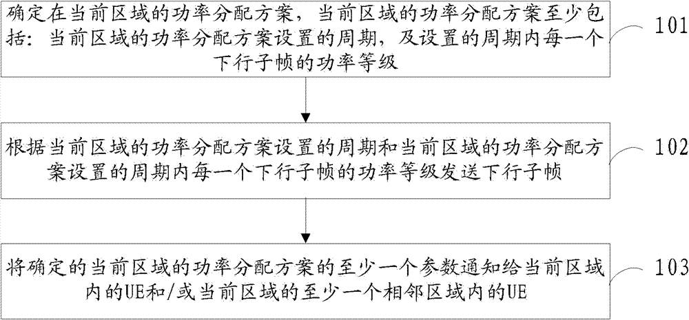
[0046] Such as figure 2 As shown, a power allocation method is described with the base station as the execution subject. A power allocation method includes:

[0047] 101. Determine the power allocation scheme in the current area, and the power allocation scheme in the current area includes at least: the period set by the power allocation scheme in the current area, and the power level of each downlink subframe within the set period;

[0048] 102. Send a downlink subframe according to the period set by the power allocation scheme of the current area...


PUM


Abstract

The invention discloses a power distribution method, a base station, user equipment and a system and belongs to the field of communication. According to the method, periods are set for a downlink power distribution scheme, transmission power levels of all subframes in all periods are set, and periods of adjacent areas of an area are equal to or in an integral multiple relationship with the period of the area, so that the base station sends downlink signals to subframes at the same position in two adjacent periods by using power of the same level, power levels of interference signals of adjacent areas are stable when the user equipment (UE) receives downlink signals at subframes at the same position in all periods, the UE is free from fluctuation phenomena when channel quality indication is measured, the good resource allocation effect and the good throughput per hour are achieved, and simultaneously, the stable receiving performance of the UE at subframes at the same position in all periods is guaranteed.

Description

technical field [0001] The present invention relates to the communication field, in particular to a power allocation method, base station, user equipment and system. Background technique [0002] In a wireless communication system, during downlink transmission, UE (User Equipment, user equipment) will measure the CQI (Channel Quality Indication, Channel Quality Indication) of downlink transmission in real time, and return the measured CQI result to its The base station at the base station will allocate resources for the UE to perform downlink transmission according to the CQI of the UE, so as to improve the effect of downlink transmission. [0003] At the same time, in a wireless communication system, in order to avoid interference to the UE by signals transmitted by base stations of adjacent cells and improve channel quality of the cell, downlink transmission power is usually allocated. The currently adopted downlink transmission power allocation scheme divides downlink tr...

Claims


Application Information

Patent Timeline
IPC IPC(8): H04W52/04H04W72/04
Inventor 夏亮孙静原
Owner HUAWEI TECH CO LTD
Learn More