Defibrillator display

A defibrillator and video display technology, applied in the direction of cardiac defibrillators, instruments, sensors, etc., can solve the problems of limited wearability and comfort, excessive size and weight of batteries, troublesome life-saving equipment, etc. effect of care

Inactive Publication Date: 2012-11-14
ZOLL MEDICAL CORPORATION
View PDF13 Cites 7 Cited by
  • Summary
  • Abstract
  • Description
  • Claims
  • Application Information

AI Technical Summary

Problems solved by technology

This results in batteries that are excessive in both size and weight, which limits their portability and convenience, and, in the case of externally wearable defibrillators such as LifeVest (ZOLL Medical, Chelmsford, MA), Limits their wearability and comfort
Additionally,

Method used


Image

  • Defibrillator display
  • Defibrillator display
  • Defibrillator display

Examples


Embodiment Construction

[0051] This specification discusses systems and techniques for delivering defibrillation energy in a controlled manner. Typically, such energy needs to be built up, for example by charging a capacitor, and this energy buildup can take a considerable time. Using the techniques described here, the system can pre-analyze the patient's need to deliver a defibrillation pulse (for example, while the rescuer is performing chest compressions), and can place a capacitor or other appropriate The energy delivery mechanism is charged so that the shock can be delivered on demand.

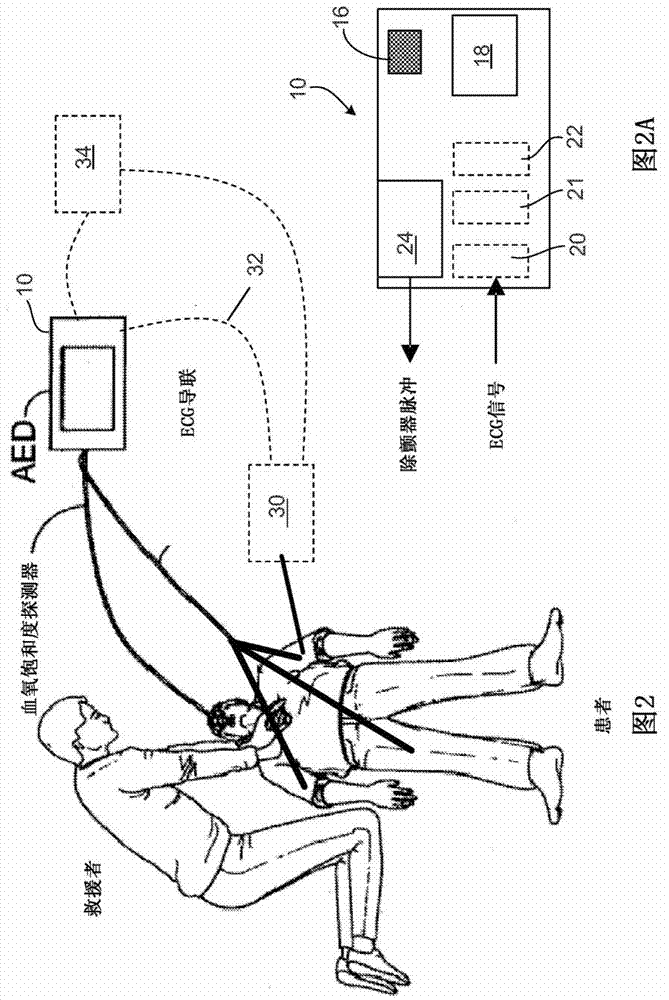
[0052] see now figure 2 , shows the AED 10, which can be used to deliver a defibrillation shock at the appropriate time. In this figure showing an example implementation, a rescuer uses AED 10 to automatically monitor a patient during cardiac resuscitation. The AED 10 uses the measured ECG signal to monitor the patient's heart and recharge the defibrillation device within the AED while resuscitating the pati...


PUM


Abstract

Systems and methods related to the field of cardiac resuscitation, and in particular to devices for assisting rescuers in performing cardio-pulmonary resuscitation (CPR) are described herein.

Description

[0001] Cross References to Related Applications [0002] This application is based on U.S. Provisional Application No. 61 / 304,119, filed February 12, 2010, entitled "DEIBRILLATOR CHARGING," and the filing on February 24, 2010, entitled "DEIBRILLATOR DISPLAY (Except Vibrator Display), the entire contents of each of which are hereby incorporated by reference. technical field [0003] This document relates to cardiac resuscitation, and in particular to systems and techniques for assisting rescuers in performing cardiopulmonary resuscitation (CPR). Background technique [0004] The heart relies on an orderly sequence of electrical impulses to beat efficiently. Deviations from this normal sequence are known as "arrhythmias". Some medical devices include signal processing software that analyzes electrocardiogram (ECG) signals taken from treated patients (for example, patients in emergency situations) to determine when conditions such as ventricular fibrillation (VF) or shockable...

Claims


Application Information

Patent Timeline
IPC IPC(8): A61N1/39G16H20/30G16Z99/00
CPCA61N1/3993A61H2230/205A61N1/3925A61H2201/5084G09B19/003A61N1/3981A61H2230/04A61N1/3937G06F19/3481A61H2230/207A61H31/005G06F19/3406A61N1/3975A61H2201/5076A61B5/082A61B5/14542A61B5/7225A61B5/7235A61B5/7257A61B5/7271A61B5/742A61N1/39A61H2230/30A61B5/318G16Z99/00G09B23/288G16H40/63G16H20/30G16H20/40G16H50/00A61B5/11A61B5/7282A61B5/746A61N1/046A61N1/0492A61N1/3931A61N1/3987A61B2562/0219A61H2201/5043A61B5/7445A61B5/339A61B5/25A61B5/0205A61B5/0836
Inventor 谭清加里·A·弗里曼弗雷德里克·J·格哈卜马丁·E·布里斯安娜玛丽·西尔弗
Owner ZOLL MEDICAL CORPORATION
Why Eureka
Try Eureka