Fiber optic interface devices for electronic devices

A technology of optical fiber interface and optical fiber interface components, which is applied in the directions of optics, light guides, optical components, etc.

Inactive Publication Date: 2012-11-14
CORNING INC
View PDF12 Cites 6 Cited by
  • Summary
  • Abstract
  • Description
  • Claims
  • Application Information

AI Technical Summary

Problems solved by technology

Further, consumer electronic devices often have

Method used


Image

  • Fiber optic interface devices for electronic devices
  • Fiber optic interface devices for electronic devices
  • Fiber optic interface devices for electronic devices

Examples


Embodiment Construction

[0030] Reference will now be made in detail to the preferred embodiments of the present disclosure, examples of which are illustrated in the accompanying drawings. Wherever possible, the same or similar reference symbols are used throughout the drawings to represent the same or like parts. Various modifications and changes may be made to the following examples within the scope of this disclosure, and aspects of different examples may be combined in various ways to arrive at still further examples. Therefore, the true scope of the disclosure should be read in its entirety in light of, but not limited to, the embodiments described herein.

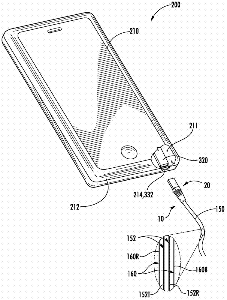
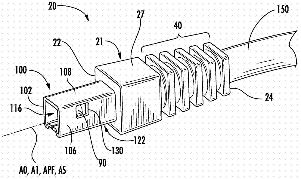
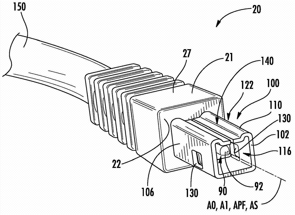
[0031] In some of the drawings, a Cartesian coordinate system is shown for reference. Meanwhile, in order to distinguish different parts of the interface device assembly, the terms "plug" and "receptacle" are used as shorthand expressions for different types of optical fiber interface devices. Further, in some examples discussed below, the ...


PUM

PropertyMeasurementUnit
Horizontal sizeaaaaaaaaaa

Abstract

Small-form-factor fiber optic interface devices (20) for electronic devices (200) are disclosed. The device has a ferrule (50) with a body (51) that operably supports at least one waveguide (152) and at least one electrical wire (160). The device has a first electrical contact (90) supported by the ferrule body and a second electrical contact (100) that substantially surrounds the outer surface (57) of the ferrule body front section (56). The ferrule body comprises a dielectric material at least partially interposed between the first and second electrical contacts.

Description


Claims


Application Information

Patent Timeline
Owner CORNING INC
Why Eureka
Try Eureka