Supercharge Your Innovation With Domain-Expert AI Agents!

Direct shearing type reinforcing assembly

A reinforcement component, shear type technology, applied in the direction of building maintenance, construction, building construction, etc., can solve the problems of large functional interference of the structure in use, reduce the clear height of the structure, increase the self-weight of the structure, etc., and achieve the reliability of reinforcement quality. High, reliable effect of eliminating radial clearance, stiffness and load-carrying capacity

Active Publication Date: 2012-11-21
全学友
View PDF6 Cites 1 Cited by
  • Summary
  • Abstract
  • Description
  • Claims
  • Application Information

AI Technical Summary

Problems solved by technology

Concrete enlarging cross-section reinforcement method will affect the appearance of components, reduce the net height of the structure, increase the self-weight of the structure, and the construction is troublesome, which greatly interferes with the function of the structure in use; the reinforcement of fiber composite materials can only increase the bearing capacity of components to a limited extent. Due to the influence of secondary stress, cracks, deflection, and peeling damage, the stress of carbon fiber panels under normal use is usually less than 5% of the standard strength, so that carbon fiber composites cannot fully play their due role, and the stiffness increases very little. It is difficult to effectively exert the high strength of the steel plate; although the reinforcement method of pasting steel plates can effectively improve the bearing capacity of the component, it is prone to peeling damage; due to the gap between the steel plate hole and the anchor bolt connected by ordinary anchor bolts, the stress on the steel plate is lagging behind, and the stiffness improvement is limited.
At the same time, pasting fiber composite materials and pasting steel plate reinforcement have common fatal shortcomings, that is, they rely too much on the treatment quality and pasting quality of the concrete base layer, and the adhesive cannot be fireproof, and even the use in a temperature environment above 60°C is restricted.

Method used


Image

  • Direct shearing type reinforcing assembly
  • Direct shearing type reinforcing assembly
  • Direct shearing type reinforcing assembly

Examples


Embodiment Construction

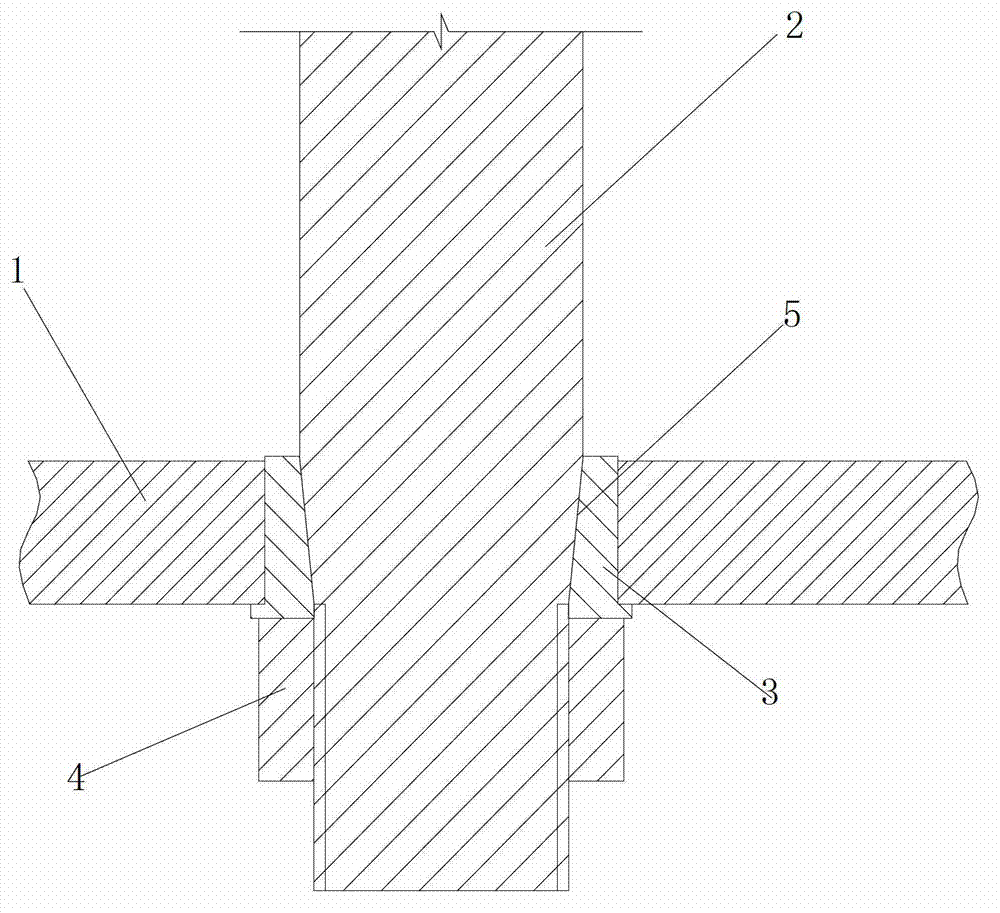
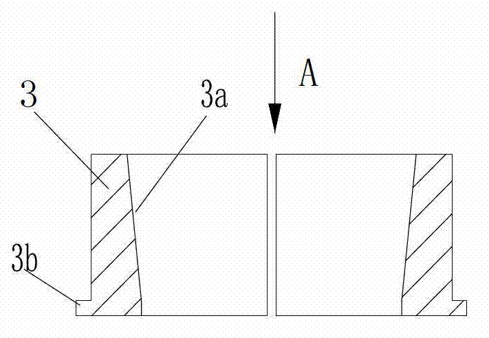
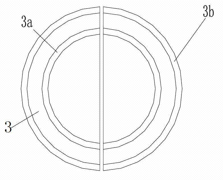
[0020] figure 1 It is a schematic diagram of the structure of the present invention, figure 2 It is a schematic diagram of the structure of the expansion sleeve of the present invention, image 3 for figure 2 View along direction A, Figure 4 It is a schematic diagram of the installation process of the present invention, Figure 5 The structural diagram is used for the present invention, as shown in the figure: the direct shear type reinforcement assembly of this embodiment includes a reinforcement plate 1 that is close to the member to be reinforced and an anchor bolt that fixes the reinforcement plate 1 to the member to be reinforced pair, the anchor bolt pair includes an anchor bolt 2, an expansion sleeve 3 and an anchor nut 4, the expansion sleeve 3 is a split structure formed by at least two half-columns, and is fitted with the anchor bolt 2 through a tapered surface pair to cover the anchor Bolt 2, the expansion sleeve 3 is pressed into the connection hole 1a of th...


PUM


Abstract

The invention provides a direct shearing type reinforcing assembly. The direct shearing type reinforcing assembly comprises a reinforcing plate and an anchor bolt pair, wherein the reinforcing plate is close to the components needing reinforcing; the anchor bolt pair is used for fixedly connecting the reinforcing plate with the components needing reinforcing; the anchor bolt pair comprises an anchor bolt, an expansion sleeve and an anchoring nut; the expansion sleeve is of a split structure formed by at least two semicylinders, and the expansion sleeve is matched with the anchor bolt through a conical pair and is sleeve out the anchor bolt; and the expansion sleeve is pressed into a connecting hole of the reinforcing plate through the anchoring nut screwed on the anchor bolt, and the external circle of the expansion sleeve is tightly matched with the connecting hole through an expansion way under the action of the conical pair. In the invention, the components needing reinforcing are used as supports of the anchor bolt, thus providing effective constraint for strengthening reinforcing assembly; the anchor bolt directly bears shearing action; the reinforcing plate directly participates in the stressing of the components, so the actions of the reinforcing plate can be completely exerted; the reinforcing quality and the reliability are high; and all anchor bolts and the reinforcing plate can jointly immediately participate in stressing in the overload stress process after the component reinforcing, so that the rigidity and the bearing capacity of the reinforced components can be reliably improved by a large margin.

Description

technical field [0001] The invention belongs to the field of civil structure engineering, and in particular relates to a direct shear reinforcement component. Background technique [0002] Concrete elements require reinforcement for various reasons. While various hardening methods exist, each method has its own limitations. Concrete enlarging cross-section reinforcement method will affect the appearance of components, reduce the net height of the structure, increase the self-weight of the structure, and the construction is troublesome, which greatly interferes with the function of the structure in use; the reinforcement of fiber composite materials can only increase the bearing capacity of components to a limited extent. Due to the influence of secondary stress, cracks, deflection, and peeling damage, the stress of carbon fiber panels under normal use is usually less than 5% of the standard strength, so that carbon fiber composites cannot fully play their due role, and the ...

Claims


Application Information

Patent Timeline
IPC IPC(8): E04G23/02
Inventor 全学友
Owner 全学友
Features
  • R&D
  • Intellectual Property
  • Life Sciences
  • Materials
  • Tech Scout
  • Unparalleled Data Quality
  • Higher Quality Content
  • 60% Fewer Hallucinations
Learn More