
Quick change joint mechanism for fluid medium

A fluid medium, fast technology, applied in mechanical equipment, pipe components, couplings, etc., to achieve the effect of easy manufacturing, automatic transfer, and smooth transfer

Active Publication Date: 2015-12-30
KEDE NUMERICAL CONTROL CO LTD
View PDF5 Cites 0 Cited by
  • Summary
  • Abstract
  • Description
  • Claims
  • Application Information

AI Technical Summary

Problems solved by technology

Through patent search and market investigation, it has not been found that there is a fast and automatic transfer joint installed in the circulation medium system of the above-mentioned equipment.

Method used


Image

  • Quick change joint mechanism for fluid medium
  • Quick change joint mechanism for fluid medium
  • Quick change joint mechanism for fluid medium

Examples


Embodiment Construction

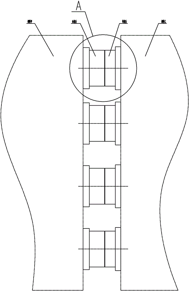
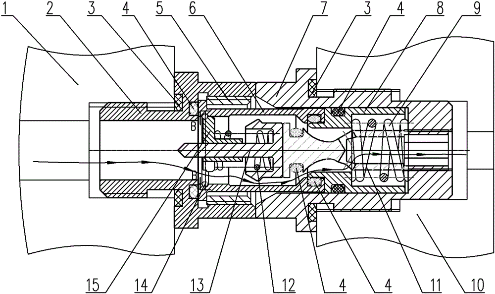
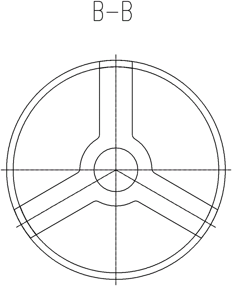
[0018] figure 1 , 2 Shown in , 3 is a specific embodiment of the present invention, which is a quick-change joint mechanism for fluid medium installed on the attachment head of the hydraulic system of the gantry milling machine. A number of combined male and female joints are installed in the middle, and each combined male and female joint is a sealed joint that is automatically formed as a whole by pushing the self-sealing male joint into the self-sealing female joint; A self-sealing male joint is mainly composed of a male housing 2, a guide ring 15, a guide sleeve 6, a piston 13, a threaded retaining sleeve 5, a spring armor 12, a sealing ring 4 and a retaining ring 14, and the connecting end of the male housing 2 is threaded Connected in Part A 1, the connection end of the male housing 2 is provided with an inlet hole for fluid medium, and the right end of the male housing 2 is provided with a penetration hole communicating with the inlet hole, and the inner bottom surface...


PUM


Abstract

The invention belongs to changing and feeding joint devices of a fluid medium and specifically relates to a rapid changing and feeding joint mechanism of the fluid medium between two separation parts when gas and liquid fluid media are in a butt joint state. The rapid changing and feeding joint mechanism is characterized in that a plurality of joints combined by male and female joints are distributed in a butt connection surface between a part A and a part B, each joint combined by the male and female joints is a seal joint which is automatically and integrally formed by pushing each self-sealing male joint into each self-sealing female joint, each self-sealing male joint is composed of a male casing, a guide ring, a guide sleeve, a piston, a thread blocking sleeve, a spring A, a seal ring and a blocking ring, and each self-sealing female joint is composed of a female casing, a sleeve, an ejector rod, a spring B and a seal ring. The rapid changing and feeding joint mechanism has the advantages that the design is reasonable, the structure is compact, besides, the mechanism is self-sealing, free of leakage and convenient to manufacture and install, the operation is safe and reliable, and the like.

Description

technical field [0001] The invention belongs to a fluid medium exchange joint device, in particular to a quick exchange joint mechanism for a fluid medium between two separate parts when the gas and liquid fluid media are in a docking state. Background technique [0002] At present, in a wide variety of metal processing and cutting equipment, usually due to the needs of processing and automatic operation, the above-mentioned processing equipment is required to be installed on the above-mentioned processing equipment to adapt to dynamic processing occasions, equipped with quick-change joint mechanisms for different fluid media, such as gantry milling machines In order to adapt to different dynamic processing occasions, it is equipped with docking attachment heads of different hydraulic systems, attachment heads for automatic replacement of machine tool swing heads... Each attachment head has multiple hydraulic lines, and its multiple hydraulic lines are usually The two separa...

Claims


Application Information

Patent Timeline
Patent Type & Authority Patents(China)
IPC IPC(8): F16L37/30F16L39/00
Inventor 蔡春刚杜长林任志辉冷磊江世琳
Owner KEDE NUMERICAL CONTROL CO LTD
Learn More